Tivoli Teardown Disappoints

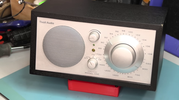
[Fran] has been curious about the innards of Tivoli Audio’s Model One radio, but was reluctant to shell out $200 just to tear it apart. But she found one recently on eBay, won the auction, and proceeded to do a review and teardown. Spoiler alert, she was disappointed.

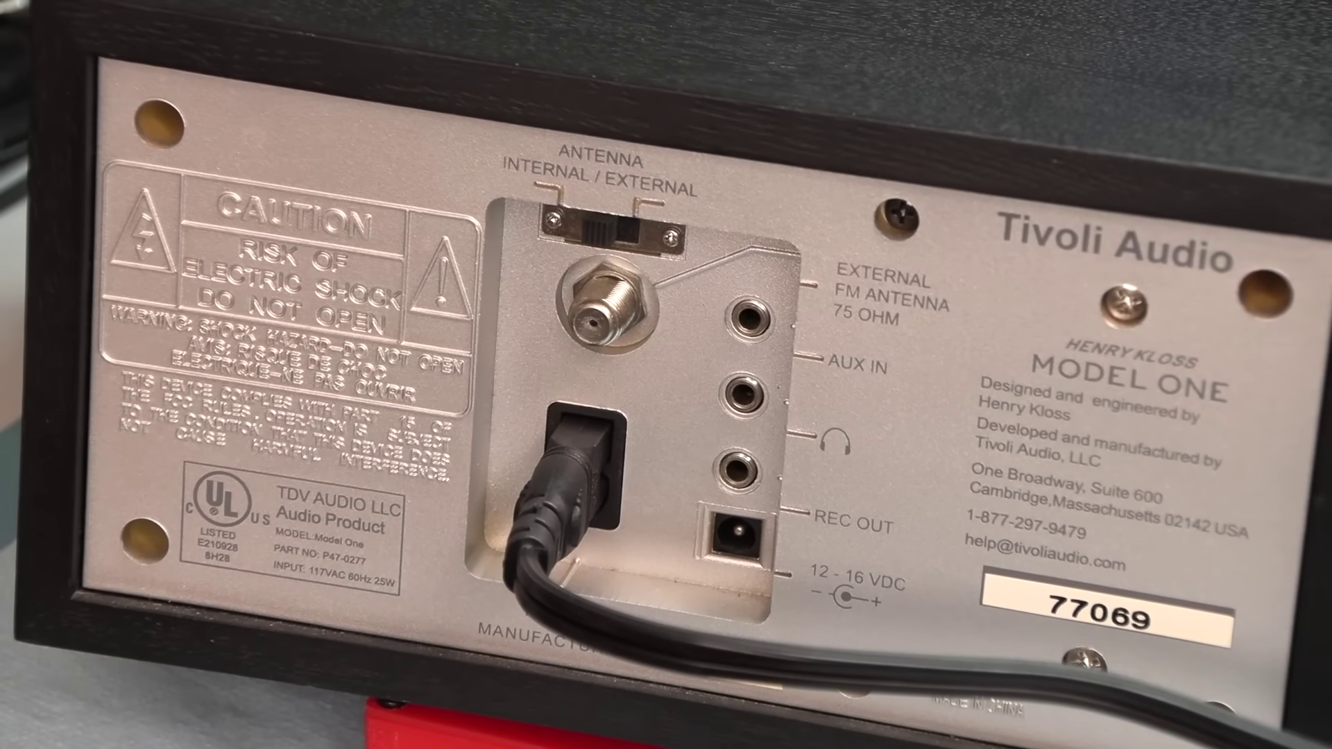
Physically speaking, the radio looks great and has quite an array of I/O connections. The geared tuning knob looks cool, but is heavily damped which [Fran] isn’t keen about. Turning it on, a few more quirks are discovered. The volume control is out-of-whack — it appears they substituted a linear taper potentiometer where a logarithmic taper was called for.

Another problem, at least in the RF-dense metropolitan areas like Philadelphia, is the FM tuner’s station-lock feature. It is so strong that it can be impossible to tune in weak stations. This is especially ironic since, according to Wikipedia, that was one of audio engineer Henry Kloss’s main goals when founding Tivoli Audio back in 2000:

Their first product was the Model One, a simple to use mid-century modern designed table top radio with a high-performance tuner, receiving FM radio in congested urban locations, while maintaining the ability to pick out distant or low power stations. Kloss had noted that the mid 60’s wave of Japanese radios lacked the ability to receive FM stations in congested locations, and this became a defining goal of his radio designs throughout his career.

Interestingly, many folks in the YouTube comments say their Model One radios have none of these issues. We wonder if [Fran] has obtained a damaged radio, or maybe a newer version produced with less attention to detail. If you have a broken Model One radio, before tossing it, consider the hack we wrote about last year, turning it into an internet radio.

Continue reading “Tivoli Teardown Disappoints”

PCIe For Hackers: Our M.2 Card Is Done

We’ve started designing a PCIe card last week, an adapter from M.2 E-key to E-key, that adds an extra link to the E-key slot it carries – useful for fully utilizing a few rare but fancy E-key cards. By now, the schematic is done, the component placement has been figured out, and we only need to route the differential pairs – should be simple, right? Buckle up.

Getting Diffpairs Done

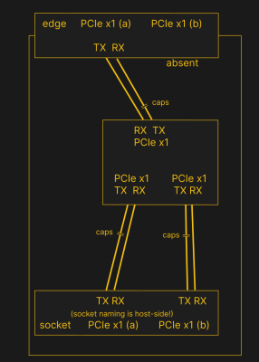
PCIe needs TX pairs connected to RX on another end, like UART – and this is non-negotiable. Connectors will use host-side naming, and vice-versa. As the diagram demonstrates, we connect the socket’s TX to chip’s RX and vice-versa; if we ever get confused, the laptop schematic is there to help us make things clear. To sum up, we only need to flip the names on the link coming to the PCIe switch, since the PCIe switch acts as a device on the card; the two links from the switch go to the E-key socket, and for that socket’s purposes, the PCIe switch acts as a host.

While initially routing this board, I absolutely forgot about one more important thing for PCIe – series capacitors on every data pair, on the host TX side of the link. We need three capacitor pairs here – on TX of the PCIe switch uplink, and two pairs on TX side of the switch – again, naming is host-side. I only remembered this after having finished routing all the diffpairs, and, after a bit of deliberation, I decided that this is my chance to try 0201 capacitors. For that, I took the footprints from [Christoph]‘s wonderful project, called “Effect of moon phase on tombstoning” – with such a name, these footprints have got to be good.

We’ve talked about differential pair calculations before in one of the PCIe articles, and there was a demo video too! That said, let’s repeat the calculations on this one – I’ll show how to get from “PCB fab website information” to “proper width and clearance diffpairs”, with a few fun shortcuts. Our setup is, once again, having signals on outer layers, referenced to the ground layer right below them. I, sadly, don’t yet understand how to calculate differential impedance for signal layers sandwiched between two ground planes, which is to say – if there’s any commenters willing to share this knowledge, I’d appreciate your input tremendously! For now, I don’t see that there’d be a tangible benefit to such an arrangement, anyway.

Continue reading “PCIe For Hackers: Our M.2 Card Is Done”

Selectric Typewriter Goes From Trash Can To Linux Terminal

If there’s only lesson to be learned from [alnwlsn]’s conversion of an IBM Selectric typewriter into a serial terminal for Linux, it’s that we’ve been hanging around the wrong garbage cans. Because that’s where he found the donor machine for this project, and it wasn’t even the first one he’s come across in the trash. The best we’ve ever done is a nasty old microwave.

For being a dumpster find, the Selectric II was actually in pretty decent shape. The first couple of minutes of the video after the break show not only the minimal repairs needed to get the typewriter back on its feet, but also a whirlwind tour of the remarkably complex mechanisms that turn keypresses into characters on the page. As it turns out, knowing how the mechanical linkages work is the secret behind converting the Selectric into a teletype, entirely within the original enclosure and with as few modifications to the existing mechanism as possible.

Keypresses are mimicked with a mere thirteen solenoids — six for the “latch interposers” that interface with the famous whiffletree mechanism that converts binary input to a specific character on the typeball, and six more that control thinks like the cycle bail and control keys. The thirteenth solenoid controls an added bell, because every good teletype needs a bell. For sensing the keypresses — this is to be a duplex terminal, after all — [alnwlsn] pulled a page from the Soviet Cold War fieldcraft manual and used opto-interrupters to monitor the positions of the latch interposers as keys are pressed, plus more for the control keys.

The electronics are pretty straightforward — a bunch of MOSFETs to drive the solenoids, plus an AVR microcontroller. The terminal speaks RS-232, as one would expect, and within the limitations of keyboard and character set differences over the 50-odd years since the Selectric was introduced, it works fantastic as a Linux terminal. The back half of the video is loaded with demos, some of which aptly demonstrate why a lot of Unix commands look the way they do, but also some neat hybrid stuff, like a ChatGPT client.

Hats off to [alnwlsn] for tackling a difficult project while maintaining the integrity of the original hardware.

Continue reading “Selectric Typewriter Goes From Trash Can To Linux Terminal”

Grab Your ‘Scope’s Screen From The Command Line

Many of us have oscilloscopes and other instruments with built-in digital interfaces, but how many of us use them? [Andrej Radović] has a Tektronix TDS2022 which can print its screen to any of its various interfaces, and he set about automating the process of acquisition with a Bash script.

The easiest interface to use was the trusty serial port — hardly the fastest but definitely the best supported. But how does one retrieve an image fired down a serial port? Most of the post is devoted to spotting file headers in a Bash script monitoring the serial port, and streaming the result to a local file. There’s a discussion of the various formats supported by the Tek, with an ancient PCX bitmap format being chosen over Postscript for speed. The result is a decent quality screen grab, making the ‘scope that little bit more useful and perhaps extending its life.

Perhaps your instrument isn’t a TEK, but the chances are you can still make it bend to your will from a PC. Try it, with the magic of VISA.