FallingWater Clock Puts New Spin On A Common LCD

Sometimes, all it takes is looking at an existing piece of tech in a new way to come up with something unique. That’s the whole idea behind FallingWater, a gorgeous Art Deco inspired clock created by [Mark Wilson] — while the vertical LCD might look like some wild custom component, it’s simply a common DM8BA10 display module that’s been rotated 90 degrees.

As demonstrated in the video below, by turning the LCD on its side, [Mark] is able to produce some visually striking animations. At the same time the display is still perfectly capable of showing letters and numbers, albeit in a single column and with noticeably wider characters.
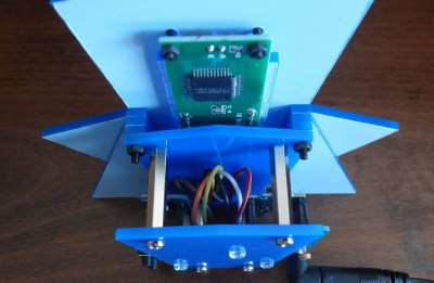
In another application it might look odd, but when combined with the “sunburst” style enclosure, it really comes together. Speaking of the enclosure, [Mark] used OpenSCAD to visualize the five layer stack-up, which was then recreated in Inkscape so it could ultimately be laser-cut from acrylic.

Rounding out the build is a “Leonardo Tiny” ATmega32U4 board, a DS3221 real-time clock (RTC), a couple of pushbuttons, and a light dependent resistor (LDR) used to dim the display when the ambient light level is low. All of the electronics are housed on a small custom PCB, making for a nicely compact package.

This build is as simple as it is stylish, and we wouldn’t be surprised if it inspired more than a few clones. At the time of writing, [Mark] hadn’t published the source code for the ATmega, but he has provided the code to generate the cut files for the enclosure, as well as the Gerber files for the PCB. If you come up with your own version of this retro-futuristic timepiece, let us know.

Continue reading “FallingWater Clock Puts New Spin On A Common LCD”

Experimental sequence for the Ramsey-type phonon anharmonicity measurement. (Credit: Yu Yang et al., Science, 2024)

Creating A Mechanical Qubit That Lasts Longer Than Other Qubits

Among the current challenges with creating quantum computers is that the timespan that a singular qubit remains coherent is quite limited, restricting their usefulness. Usually such qubits consist of an electromagnetic resonator (boson), which have the advantage of possessing discrete energy states that lend themselves well to the anharmonicity required for qubits. Using mechanical resonators would be beneficial due to the generally slower decoherence rate, but these have oscillations (phonons) that are harmonic in nature. Now researchers may have found a way to use both electromagnetic qubits and mechanical resonators to create a hybrid form that acts like a mechanical qubit, with quite long (200 µs) coherence time.

As per the research paper by [Yu Yang] and colleagues in Science (open access preprint), their experimental mechanical qubit (piezoelectric disc and superconducting qubit on sapphire) was able to be initialized and read out, with single-qubit gates demonstrated. The experimental sequence for the phonon anharmonicity measurement is shown in the above image (figure 2 in the paper), including the iSWAP operations which initialize the hybrid qubit. Effectively this demonstrates the viability of such a hybrid, mechanical qubit, even if this experimental version is not impressive yet compared to the best electromagnetic qubit. Those have managed to hit a coherence time of 1 ms.

The lead researcher, [Yu Yang] expresses his confidence that they can improve this coherence time with more optimized designs and materials, with future experiments likely to involve more complex quantum gates as well as sensor designs.

Playing Around With The MH-CD42 Charger Board

If you’ve ever worked with adding lithium-ion batteries to one of your projects, you’ve likely spent some quality time with a TP4056. Whether you implemented the circuit yourself, or took the easy way out and picked up one of the dirt cheap modules available online, the battery management IC is simple to work with and gets the job done.

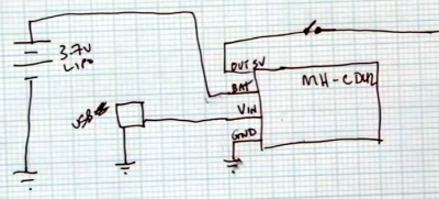
But there’s always room for improvement. In a recent video, [Det] and [Rich] from Learn Electronics Repair go over using a more modern battery management board that’s sold online as the MH-CD42. This board, which is generally based on a clone of the IP5306, seems intended for USB battery banks — but as it so happens, plenty of projects that makers and hardware hackers work on have very similar requirements.

So not only will the MH-CD42 charge your lithium-ion cells when given a nominal USB input voltage (4.5 – 5 VDC), it will also provide essential protections for the battery. That means looking out for short circuits, over-charge, and over-discharge conditions. It can charge at up to 2 A (up from 1 A on the TP4056), and includes a handy LED “battery gauge” on the board. But perhaps best of all for our purposes, it includes the necessary circuitry to boost the output from the battery up to 5 V.

If there’s a downside to this board, it’s that it has an automatic cut-off for when it thinks you’ve finished using it; a feature inherited from its USB battery bank origins. In practice, that means this board might not be the right choice for projects that aren’t drawing more than a hundred milliamps or so.

Continue reading “Playing Around With The MH-CD42 Charger Board”

Lathe Gears Make A Clock

When you think of making something using a lathe,  you usually think of turning a screw, a table leg, or a toothpick. [Uri Tuchman] had a different idea. He wanted to make a clock out of the gears used in the lathe. Can he do it? Of course, as you can see in the video below.

Along the way, he used several tools. A mill, a laser cutter, and a variety of hand tools all make appearances. There’s also plenty of CAD. Oh yeah, he uses a lathe, too.

Continue reading “Lathe Gears Make A Clock”

20 GHz LNB Testing And Teardown

Many things have combined to make very high-frequency RF gear much more common, cheaper, and better performing. Case in point: [dereksgc] is tearing apart a 20 GHz low-noise block (LNB). An LNB is a downconverter, and this one is used for some Irish satellite TV services.

The scale of everything matters when your wavelength is only 15 mm. The PCB is small and neatly laid out. There are two waveguides printed on the board, each feeding essentially identical parts of the PCB. Printed filters use little patterns on the board that have particular inductance and capacitance — no need for any components. Try doing that at 2 MHz!

The LNB is a single-band unit, so it only needs to worry about the two polarizations. However, [dereksgc] shows that some have multiple bands, which makes everything more complex. He also mentions that this LNB doesn’t use a PLL, and he’d like to find a replacement at this frequency that is a bit more modern.

After the teardown, it is time to test the device to see how it works. If you want to experiment at this frequency, you need special techniques. For example, we’ve seen people try to push solderless breadboards this high (spoiler: it isn’t easy). Maybe that’s why many people settle for modifying existing LNBs like this one.

Continue reading “20 GHz LNB Testing And Teardown”

Do You Know Vail Code?

Alfred Vail (public domain)

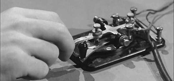
We talk about Morse code, named after its inventor, Samuel Morse. However, maybe we should call it Vail code after Alfred Vail, who may be its real inventor. Haven’t heard of him? You aren’t alone. Yet he was behind the first telegraph key and improved other parts of the fledgling telegraph system.

The story starts in 1837 when Vail visited his old school, New York University, and attended one of Morse’s early telegraph experiments. His family owned Speedwell Ironworks, and he was an experienced machinist. Sensing an opportunity, he arranged with Morse to take a 25% interest in the technology, and in return, Vail would produce the necessary devices at the Ironworks. Vail split his interest with his brother George.

By 1838, a two-mile cable carried a signal from the Speedwell Ironworks. Morse and Vail demonstrated the system to President Van Buren and members of Congress. In 1844, Congress awarded Morse $30,000 to build a line from Washington to Baltimore. That was the same year Morse sent the famous message “What Hath God Wrought?” Who received and responded to that message? Alfred Vail.

The Original Telegraph

Telegraphs were first proposed in the late 1700s, using 26 wires, one for each letter of the alphabet. Later improvements by Wheatstone and Cooke reduced the number of wires to five, but that still wasn’t very practical.

Samuel Morse, an artist by trade, was convinced he could reduce the number of wires to one. By 1832, he had a crude prototype using a homemade battery and a relatively weak Sturgeon electromagnet.

Continue reading “Do You Know Vail Code?”

desk with a hand holding a Lego unit

LDU Decoded: The Untold Tale Of LEGO Dimensions

LEGO bricks might look simplistic, but did you know there’s an actual science behind their sizes? Enter LDUs — LEGO Draw Units — the minuscule measurement standard that allows those tiny interlocking pieces to fit together seamlessly. In a recent video [Brick Sculpt] breaks down this fascinating topic.

So, what is an LDU precisely? It’s the smallest incremental size used to define LEGO’s dimensions. For context, a standard LEGO brick is 20 LDUs wide, and a single plate is 8 LDUs tall. Intriguingly, through clever combinations of headlight bricks, jumper plates, and even rare Minifig neck brackets, builders can achieve offsets as tiny as 1 LDU! That’s the secret sauce behind those impossibly detailed LEGO creations.

We already knew that LEGO is far more than a toy, but this solidifies that theory. It’s a means of constructing for anyone with an open mind – on its own scale. The video below explains in detail how to achieve every dimension possible. If that inspires you to build anything, dive into these articles and see if you can build upon this discovery!

Continue reading “LDU Decoded: The Untold Tale Of LEGO Dimensions”