Although the CRT has largely disappeared from our everyday lives, there was a decades-long timeframe when this was effectively the only display available. It’s an analog display for an analog world, and now that almost everything electronic is digital, these amazing pieces of technology are largely relegated to retro gaming and a few other niche uses. [Maurycy] has a unique CRT that’s small enough to fit in a handheld television, but since there aren’t analog TV stations anymore, he decided to build his own with nothing but an 8-bit microcontroller and a few other small parts.
The microcontroller in question is a fairly standard 8-bit AVR. These microcontrollers have one major limitation when generating the VHF and UHF radio signals needed for analog TV: their natural clock speed is much too low. The maximum output frequency of a pin on this microcontroller is only 6 MHz, and [Maurycy] needs something about two orders of magnitude faster. To solve this problem, [Maurycy] uses a quirk of the square wave generated by toggling a pin at its maximum frequency, which is that a wide range of harmonics will be generated, some of which will have a high enough frequency to be picked up on the handheld analog TV. The microcontroller is configured to use two pins. Toggling the pins into various states allows the humble AVR to generate a usable TV signal.
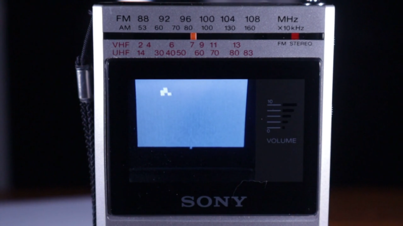
The scan rate for CRTs is comparably low as well. At the beginning of each frame, there’s enough processing power left on the microcontroller to play Conway’s Game of Life, which is then sent out over the airwaves to the TV. [Maurycy] notes that his harmonics-based video generation method is extremely noisy and probably wouldn’t pass FCC muster. However, the signal Power is so low that it’s unlikely to interfere with anything. If you’re curious about these unusual sideways-built CRTs, though, we recently saw someone take two apart and use them to build a CRT-based VR headset.


Legitimately cool project.
While perhaps not so small, these tubes are of the video doorbell type, which (astonishingly) is in stock on AliX.
Emitting radio signals without license is a federal crime because you can interfere with emergency stuff (like 911 calls and dispatch).
I doubt this transmitts any longer distance.
A few feet.
From the original page:
“The image is surprisingly good for how hacky the transmitter is, and can be received ten meters away”.
For unaware people, that is about 30 feet.
If the video signal on the 33rd harmonic is going that far, the lower harmonics are probably going a lot further. Some of those harmonics will be in the VHF aircraft band.
Assuming you mean the US, that’s not true as stated. There are bands that don’t require a license at all, especially below any level of power this can put out driving its pins. Granted, broadcast television channels aren’t within any of those bands. True that it can (and likely will) interfere outside intended band without filters due to harmonics. However, all of this could be negated by simply using the television’s antenna terminals and pumping the (attenuated!) signal directly over wire. Even better if it has coax input. Source: actual licensed (sufficient to build and use my own transmitter on “world” bands) radio operator.
“Granted, broadcast television channels aren’t within any of those bands.”
That’s not true.
https://share.google/aimode/DpaY7iZpxqCXg5Xs0
i cant imagine the tx power being all that high. enough to get across the room perhaps. too weak to count as a source of interference. its moot if he is using a hard connection.
Here in the US we have part 15 for that.
I’m not sure this device conforms to it. But it does exist.
What country do you live in that has no provisions for unlicensed low power emitters of rf????
You don’t have wireless anything in your country that doesn’t require licensing to operate?
I’d move!
Fun little project.
Useful to recall the ZX80 did it with a 3.25 MHz processor.
Now, I knew I was keeping those channel 3/4 RF modulators around for a reason.
Off to AliEx to fetch me a CRT or two. Then I can skip even the RF modulator.
The cute/bizarre thing here is that he says he’s “just” emitting a 6MHz square wave, and relying on sharp enough edges from the pin drivers to emit loud enough noise at the 29x harmonic to be decoded as System-M channel 7. (Nominal 175.25MHz, actually sending at 174MHz).
But why channel 7? If he’s starting with 6MHz, he should get better results on all of channel 2 (9x harmonic, 54MHz should be 55.25), channel 4 (11x harmonic, 66MHz should be 67.25), and channel 5 (13x harmonic, 78MHz should be 77.25).
The amount of signal up at 29x should be minimal, and yet he’s showing good reception. It seems far more likely that his receiver is badly out of calibration…
Agreed on all that. I can only assume that “few cm of wire” he uses as an antenna is much more efficient at the higher frequencies. Likewise the receiver’s antenna.
The whole contraption radiates, not just the “few cm of wire”. RF is a bitch.
avrs can usually go up to 20 mhz if not more. you can get 12 and 18 mhz crystals which might better hit the harmonic. idk im not really a radio nerd. i presume he picked 6mhz for a reason.
Author here, the circuit is in fact transmitting on >200 MHz, as confirmed by two spectrum analyzers and multiple radio receivers.
The best range was actually at lower frequencies. At ten meters, with some fiddling around to find the strongest signal and best antenna position, the image is very noisy but it is still clearly there. I was testing in a remote area, so the band was fairly quiet and even a microscopic amount of power can carry quite far.
Sure, it sounds crazy, but with 4 different radios and 2 different spectrum analyzers agreeing (and a using a signal generator to check that the TV’s tuning indicator is correct), I think the sensible conclusion is that digital devices are really that noisy. There’s a reason the FCC regulates anything with a computer in it: Interference from digital devices is far from a theoretical concern.
back in the day almost all 8 bits micro generated video with mostly software. jupiter ace was one of simpler circuit?
I don’t know about Jupiter Ace, but I don’t think this is true in general. For one, they had video modulators. But they usually also had a separate image generation chip (e.g.,, ULA in ZX Spectrum / ZX 81), or the equivalent implemented with discrete logic outside the CPU (I think that was the case for ZX 80).
I recall my parents calling to turn the C64 off when they wanted to watch television in the next room.
I have yet to see one that can do it entirely in software. Z80 and 6502 are much too slow to wiggle a port pin fast enough for direct video generation. The best you could do with these chips was to create frame/line timing and a sequence of memory addresses. The heavy lifting was always done by a shift register surrounded by some strange control circuitry.
if you just wanted a composite signal, there was an old arduino library for that, required like 3 components to hook it to a tv.
its something else entirely to come up with a signal you can transmit.