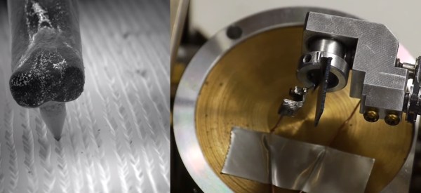
[SuperUnknown] has revealed a secret project he’s been working on. He’s cooked up an EDM attachment for 3D printers, or any CNC machine for that matter. Electrical Discharge Machining (EDM) is a method of using sparks to machine metal. EDM isn’t a new technology, in fact commercial machines have been around since the 1960’s. If you’ve ever had an arc scar up your multimeter probes, you’ve unwittingly done a bit of EDM.
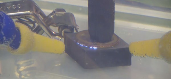
The theory behind EDM is simple: High voltage between the tool and workpiece causes sparks to jump between them. Each spark erodes the workpiece (and the tool). Big EDM machines perform their magic in a liquid which acts as both a dielectric and a flushing medium. This liquid can be anything from deionzed tap water to specially formulated oil. [SuperUnknown] is using good old-fashioned tap water.
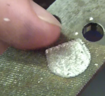 As you can imagine, a single spark won’t erode much metal. EDM machines fire tens of thousands of times per second. The exact frequencies, voltages, and currents are secrets the machine manufacturers keep close to their chests. [SuperUnknown] is zeroing in on 65 volts at 2 amps, running at 35 kHz. He’s made some great progress, gouging into hardened files, removing broken taps from brass, and even eroding the impression of a coin in steel.
While we’d love to say this is a free open source project, [superUnknown] needs to pay the bills. He’s going with crowdsourced funding. No, not another Kickstarter. This project is taking a different route. The videos of the machine will be uploaded to YouTube and visible to [superUnknown’s] Patreon supporters. They will also be available for rent using YouTube’s new rental system. [SuperUnknown] has pledged to figure out a way to make the content available for starving college students and others with limited incomes.
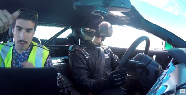
Based upon his previous adventures with lil’ screwy, his homemade 100 ton press, and various other projects on the Arduino verses Evil YouTube channel, we think [superUnkown] has a pretty good chance of making home EDM work. Click past the break to see two videos of the 3D printer EDM toolhead in action. We should mention that [SuperUnknown] is rather colorful with his dialogue, so make sure you’re using headphones if you’re at work.
Continue reading “Machine Metal With Electricity: An EDM Attachment For 3D Printers”

 . Vinyl is an insulator. [Ben] dealt with this by using his vacuum chamber to evaporate a thin layer of silver on the vinyl.
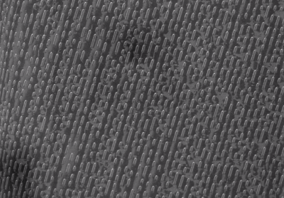 [Ben] wasn’t done though. He checked out a few other recording formats, including CD and DVD optical media, and

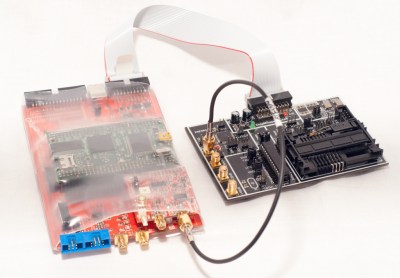
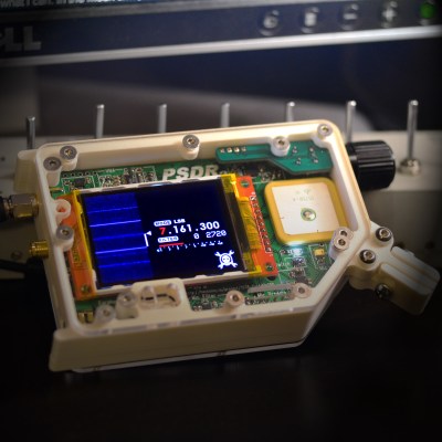 Next up is [Michael R Colton] with PortableSDR. PortableSDR was one of the five finalists in The 2014 Hackaday Prize. This pocket-sized software defined radio transceiver started as a ham radio project: a radio system which would be easy for hams to take with them on backpacking trips. It’s grown into so much more now, with software defined radio reception and transmission, vector network analysis, antenna analysis, GPS, and a host of other features. [Michael] raised a whopping $66,197 in his