

The Hackaday Prize is heating up! When we set up the prize, we expected to see some incredible entries, and you guys haven’t let us down. Projects like SatNOGS, which aims to create a global network of satellite ground stations, or OpenMV, a low-cost Python powered vision module, are seriously blowing us away.
We’re starting to give away some prizes through community voting and there’s still plenty of time for you to enter. Check out The Hackaday Prize page for the full details.
Low Cost Printed Circuit Board Tools

We’ve seen mills, lathes, CNC machines and 3D printers, but if there is any device that gets a hardware hacker’s attention, it’s a pick and place machine. In the PCB industry these machines pick up thousands of parts every hour, perfectly placing them on printed circuit boards. The downside is they’re incredibly expensive. The cheapest Chinese machines without vision start in the $4000 USD price range.
[Neil] aims to break down those price barriers with a $300 Pick and Place Machine that doubles as a 3D printer. He’s using delta 3D printer hardware to do it, and he’s throwing in everything! OpenCV based vision, multiple tool heads, reel and tray pick up, [Neil] has covered all the major points. He can’t do it alone though, so he’s looking for help. Check it out, and give him a hand (or a skull)!
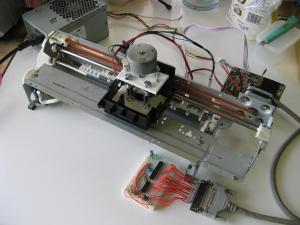
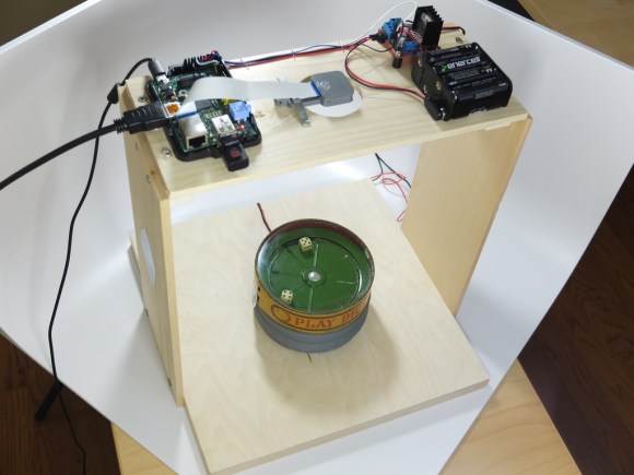
A low-cost pick and place machine will need printed circuit boards to work on. Not to worry, [shlonkin] has you covered with his PCB mill for under $10. Built from recycled printers, an Arduino, and host software written in processing, [shlonkin] has already posted impressive photos of boards his machine has milled. The main problem [shlonkin] has run into is longevity with plastic parts. In his most recent update, he’s looking for ideas. Can you help him?
Digital Watches
Anyone will tell you that digital watches are a pretty neat idea. With the era of smartwatches upon us, more than one hacker has delved into building their own timepiece. We’re happy to report that most of them even tell time.
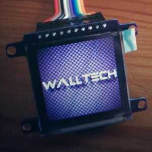 [Walltech] has gone all out to create the ultimate watch. His OLED Smart Watch 6.0 is the culmination of years of work. The watch features a 1.5” OLED display, an SD card slot, and a vibrator motor. It has Bluetooth 4.0 to connect to the world, and an Atmel ATmega32u4 as its brain. A 500mAh battery will power the watch for 18-24 hours per charge.
[Walltech] plans to make it do everything from SMS and email notifications to music streaming. Don’t see a feature you want? Add it! Smart Watch 6.0 Is completely open source, so you can hop into the code and hack away!
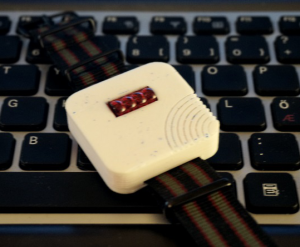 On the other side of the spectrum is [askoog89’s] Tilt Touch Time, which utilizes those awesome bubble LED displays some of us remember from the 70’s. The retro look is only 3D printed skin deep though, as [askoog89] is using an ATtiny2313 processor. Atmel’s Qtouch is providing the capacitive touch sensing, while a tilt sensor helps Tilt Touch Time live up to its name. [Askoog89] has submitted his watch to The Hackaday Prize, so he’s trying to figure out a way to use the touch sensor to sync time with a PC. If that doesn’t work out, we bet those bubble LEDs would make great light sensors for some monitor-blink-sync action.
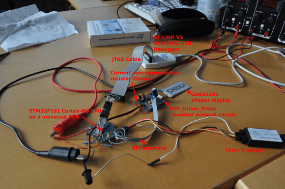
Fallout fans have seen plenty of PIP boys here on Hackaday, but have you seen [jara’s] PIP Watch? This Personal Information Panel is going big on size but low on power with a 3 inch e-ink display. [Jara] is using an STM32F101 ARM Cortex-M3 CPU, so he’s got plenty of processing power at his disposal. He’s connecting to the world through a Bluetooth serial link. All he needs is a Geiger counter, and he’s good to go!
That’s it for this week’s Hacklet, stay tuned for next week when we bring you more of what’s happening at Hackaday.io!
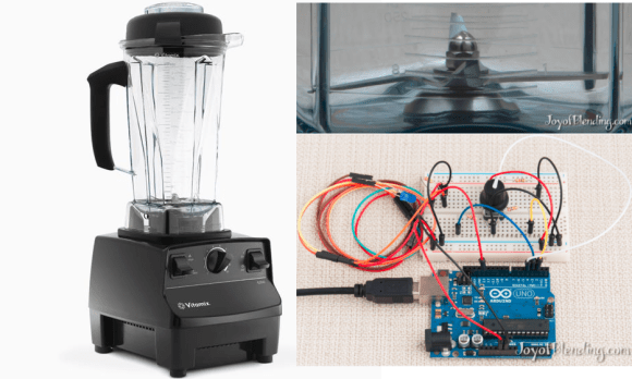 Some people really love their smoothies. We mean really, really, love smoothies and everything about making them, especially the blenders. [Adam] is a big fan of blenders, and wanted to verify that his Vitamix blenders ran as fast as the manufacturer claimed. So he built not one, but
 Behind a nondescript loading dock in Brooklyn stands a normal looking brick building. Go up 3 narrow flights of stairs – you’ll find yourself at the door to the awesome known as
 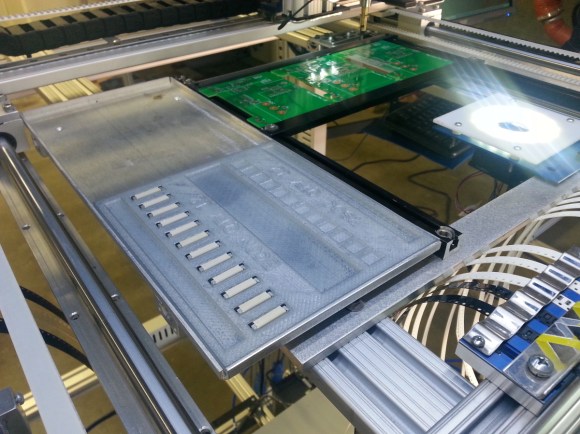 Pick and Place machines are one of the double-edged swords of electronics.They build your boards fast, but if you don’t have everything setup perfectly, they’ll quickly make a mess. A pick and place can’t grab a resistor from a pile and place it – so far only humans can pull that one off. They need parts organized and oriented in reels or trays.


