3D Printed Trays For Your Pick And Place Machine

3dprintedPNPTray Pick and Place machines are one of the double-edged swords of electronics.They build your boards fast, but if you don’t have everything setup perfectly, they’ll quickly make a mess. A pick and place can’t grab a resistor from a pile and place it – so far only humans can pull that one off. They need parts organized and oriented in reels or trays.

[Parker Dillmann] had to load some parts, but didn’t have a tray for them, so he 3D printed his own. [Parker] works at a small assembly house in Texas. He’s working on a top secret design which includes FFC connectors. Unfortunately, the connectors shipped in pick and place unfriendly tubes rather than reels. If he couldn’t find a tray, [Parker] would have to hand place those connectors as a second operation, which would increase the time to build each board and leave more chances for mistakes.

Rather than place each part by hand, [Parker] got in touch with his friend [Chris Kraft] who is something of a 3D printing guru. [Chris] confirmed that a 3D printed tray would be possible, though the PLA he prints with was not static safe. That was fine for the connectors, but [Parker] was hoping to save some tray space by putting his PSOC4 chips in the printed tray as well.

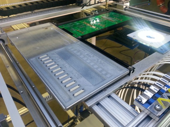
[Parker] used SketchUp to design a tray that would fit his Madell DP2006-2 pick and place. He left .15mm clearance around the parts – just enough to cover any inaccuracies during printing, but not enough to throw off parts placement. He sent the STL file over to [Chris] who used Simplify3D to a create a Gcode file. [Chris] printed the tray at .2 mm layer height on his MakerGear M2 printer, and the results looked great. Would they be good enough for the pick and place machine?

[Parker] received the printed trays in the mail and loaded them with parts. The pick and place had no problem finding and placing the connectors, making this job a huge success. [Parker] even left room for the PSOC4 chips.He plans to paint the tray with anti-static paint before giving them at try.

We really like this story – it’s a perfect example of how 3D printers can speed up processes in manufacturing. Now that the basic design is done, creating new trays is a snap. Nice work [Parker] and [Chris]! Continue reading “3D Printed Trays For Your Pick And Place Machine” →

A Bicycle Built For One

diyBike

[Bcmanucd] must have been vying for husband of the year when he set out to build his wife a custom time trials bicycle. We’re not just talking about bolting together a few parts either – he designed, cut, welded, and painted the entire frame from scratch. Time trial racing is a very specific form of bicycle racing. Bikes are built for speed, but drafting is not allowed, so aerodynamics of the bike and rider become key. Custom bikes cost many thousands of dollars, but as poor college students, neither [Bcmanucd] nor his wife could afford a proper bike. Thus the bicycle project was born.

[Bcmanucd] created the basic geometry on a fit assessment provided by his wife’s cycling coach. He designed the entire bike in Autodesk Inventor. Once the design was complete, it was time to order materials. 7005 aluminum alloy was chosen because it wouldn’t require solution heat treating, just a trip to the oven to relieve welding stresses. Every tube utilized a unique cross section to reduce drag, so [Bcmanucd] had to order his raw material from specialty bike suppliers.

Once all the material was in, [Bcmanucd] put his mechanical engineering degree aside and put on his work gloves. Like all students, he had access to the UC Davis machine shop. He used the shop’s CNC modified Bridgeport mill to cut the head tube and dropouts.

The most delicate part of the process is aligning all the parts and welding. Not a problem for [Bcmanucd], as  he used a laser table and his own jigs to keep everything lined up perfectly. Any welder will tell you that working with aluminum takes some experience. Since this was [Bcmanucd’s] first major aluminum project, he ran several tests on scrap metal to ensure he had the right setup on his TIG welder. The welds cleaned up nicely and proved to be strong.

The entire build took about 3 months, which was just in time for the first race of the season. In fact, during the first few races the bike wasn’t even painted yet. [Bcmanucd’s] wife didn’t seem to mind though, as she rode it to win the woman’s team time trial national championships that year. The bike went on to become a “rolling resume” for [Bcmanucd], and helped him land his dream job in the bicycle industry.

Echoing the top comment over on [Bcmanucd’s] Reddit thread, we’d like to say awesome job — but slow down, you’re making all us lazy spouses look bad!

Droning On: Choosing A Flight Controller

do4 The flight controller is the nerve center of a drone. Drone flight control systems are many and varied. From GPS enabled autopilot systems flown via two way telemetry links to basic stabilization systems using hobby grade radio control hardware, there is an open source project for you.

Modern drone flight controllers can trace their roots back to R/C helicopters. Historically, R/C planes were controlled directly by the pilot’s radio. Helicopters added a new wrinkle to the mix: tail rotors. Helicopters use their tail (or anti-torque) rotor to counteract the torque of the main rotor attempting to spin the entire helicopter’s body. It all works great when the helicopter is hovering, but what about when the pilot throttles up to fly out? As the pilot throttles up, the torque increases, which causes the entire helicopter to do a pirouette or two, until the torque levels out again. The effect has caused more than one beginner pilot to come nose to nose with their R/C heli.

The solution to this problem was gyroscopes, heavy brass spinning weights that tilted in response to the helicopter’s motion. A hall effect sensor would detect that tilt and command the tail rotor to counteract the helicopter’s rotation. As the years wore on, mechanical gyros were replaced by solid state MEMS gyros. Microcontrollers entered the picture and brought with them advanced processing techniques. Heading hold gyros were then introduced. Whereas older “rate only” gyros would drift, weathervane, and wiggle, heading hold gyros would lock down the helicopter’s nose until the pilot commanded a turn. These single axis flight controllers were quickly adopted by the R/C helicopter community.

Today’s flight control systems have many sensors available to them – GPS, barometric pressure sensors, airspeed sensors, the list goes on. The major contributors to the flight calculations are still the gyros, coupled with accelerometers. As the name implies, accelerometers measure acceleration – be it due to gravity, a high G turn, or stopping force. Accelerometers aren’t enough though – An accelerometer in free fall will measure 0 G’s. Turning forces will confuse a system trying to operate solely on accelerometer data. That’s where gyros come in. Gyros measure rate of rotation about an axis. Just as our helicopter example above covered yaw, gyros can be used to measure pitch and roll of an aircraft. A great comparison of gyros and accelerometers is presented in this video from InvenSense.

Stay with us after the break for a tour of available flight controllers and what each adds to the mix. Continue reading “Droning On: Choosing A Flight Controller” →

Velociraptor Robot Ready To Run With The Big Dogs

velociraptor-robot

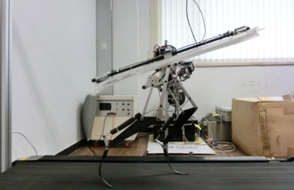
[Jongwon Park] and his team of students at the Korea Advanced Institute of Science and Technology have created a fast biped robot based upon the Velociraptor. Raptor weighs in at just 3Kg, and stands only 470mm tall, yet it is capable of running at 46 km/h. That’s almost as fast as Boston Dynamic’s Cheetah.

Raptor uses carbon fiber composite legs to absorb and release energy while running. The system is similar to that used in high performance prosthetic legs. A rotating tail assembly further helps to balance Raptor on rough terrain. We have to admit, the tail system does look a bit dangerous for any humans who might need to interact with the robot. It does work though, as evidenced by Raptor bounding over Styrofoam blocks.

The Raptor robot is quite impressive when running at full speed. Considering this project’s budget was nowhere near the resources of Boston Dynamics, it’s an amazing accomplishment. The video reminds us of  Boston Dynamics founder [Marc Raibert’s] early robots at the MIT Leg Lab. We can’t wait to see what this team produces in the future.

Continue reading “Velociraptor Robot Ready To Run With The Big Dogs” →

Meet Jimmy: An Open Source Biped Robot From Intel

Jimmy_Arm_Up

Intel’s CEO [Brian Krzanich] stopped by the Re/Code conference to announce Jimmy, the first robot from the 21st Century Robot project. The project is the brainchild of [Brian David Johnson], Intel’s resident futurist. We love the project’s manifesto:

 Robot Is: Imagined first. Easy to build. Completely open source. Fiercely social. Intentionally iterative. Filled with humanity and dreams. Thinking for her/him/itself.

Jimmy may not be all those things yet, but he definitely is exciting. For starters, he wasn’t built in some secret lab at Intel HQ. Much of Jimmy’s construction took place at Trossen Robotics, a name well known to Hackaday. [Matt] and [Andrew] at Trossen describe all the details in their video down past the break.

This version of Jimmy is a research robot, which mean’s he’s not going to come cheap. Jimmy sports an Intel i5 NUC motherboard, 20 Dynamixel servos, a 5052 aluminum frame and a host of sensors. A  4S 14.8v 4000mAh LiPo battery will power Jimmy for 30 to 60 minutes between charges, so be sure to budget for a few spare packs. The most striking aspect of Jimmy is his 3D printed shell. The 21st Century Robot Project gave him large, friendly eyes and features, which will definitely help with the social aspect of their goals.

Jimmy is all about open source. He can run two flavors of Linux: Ubuntu 14.04 LTS or a custom version of Yocto Pokey. There is a lot to be said for running and developing on the same hardware. No specialized toolchains for cross compiling, no NFS shares to move binaries around. If you need to make a change, you can plug a monitor (or launch an VNC session) and do everything with Jimmy’s on-board computer. Jimmy’s software stack is based upon the DARwIn OP platform, and a ROS port is in the works.

We’re excited about Jimmy, but at $16,000 USD, he’s a bit outside our budget. Thankfully a smaller consumer version of Jimmy will soon be available for around 1/10th the cost.

Continue reading “Meet Jimmy: An Open Source Biped Robot From Intel” →

Man Builds Concrete 3D Printer In His Garage

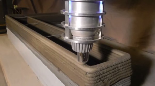
[Andrey Rudenko] is building a house in his garage. Not with nails and lumber, but with concrete extruded by his 3D printer. We’ve seen concrete 3D printers in the past, but unlike those projects, [Andrey] isn’t part of a of a university or corporation. He’s just a contractor with a dream. His printer is directly derived from the RepRap project. It’s even commanded by Pronterface.

[Andrey] started with an Arduino Mega 2560 based RepRap RAMPS style controller. His big printer needed big NEMA34 stepper motors, far beyond the current capacity of the stock RAMPS stepper drivers. [Andrey] got in touch with [James] at MassMind who helped him with an open source THB6064AH based driver. [James] even came up with an adaptor cable and PCB which makes the new drivers a drop-in replacement.

Now that his printer was moving, [Andrey] needed a material to print. Concrete chemistry is a science all its own. There are many specialty blends of concrete with specific strength and drying times. Trucking in custom mixtures can get expensive. [Andrey] has come up with his own mixture based on bags of regular concrete mix, sand, and some additives. [Andrey’s] special sauce doesn’t cure especially quickly, but it is viscous enough to print with.

Every piece of [Andrey’s] printer had to be designed and refined, including the nozzle. The concrete printer works somewhat like a frostruder, extruding concrete in 20mm wide by 5mm tall layers. He’s even managed to print overhanging layers and arches exactly like a giant RepRap Mendel.

The printer’s great unveiling will be this summer. [Andrey] plans to print a playhouse sized castle over the course of a week. He’s looking to collaborate with architects, builders, and other like-minded folks. We’d suggest uploading the project to  Hackaday.io!

Continue reading “Man Builds Concrete 3D Printer In His Garage” →

[Ken Shirriff] Explains The TL431

[Ken Shirriff] had to get down into a bit of semiconductor physics to give us an explanation of the TL431, which he calls “the most common chip you’ve never heard of”. [Ken] may well be right about the TL431. Even Texas Instruments can’t nail down a single name for it. Their page for the part calls it a “Adjustable Precision Shunt Regulator”, yet the datasheet is titled “Precision Programmable Reference”. You’d think they’d have figured this out by now, considering the TL431 was launched in 1978.

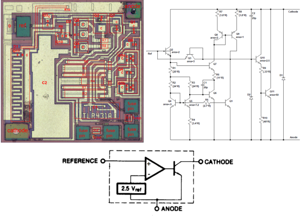
TL431’s can most often be found hiding in switching power supplies. The Apple II switcher had one, and many current ATX supplies have 3. Uninformed parts scroungers may miss them, as they often hide in TO-92 or SOT-23 packages. The TL431 is no transistor though. The TL431’s operation is actually pretty simple. When the voltage at the reference pin is above 2.5V, the output transistor conducts. When the reference voltage falls below 2.5V, the device stops conducting. In a power supply, this operation would help the control electronics maintain a stable output voltage.

The real subject of [Ken’s] article is the layout of the TL431 on its silicon die.  Rather than bust out the fuming nitric acid himself, [Ken] uses some of [Zeptobars’] decapped chip images. Inside the TL431, [Ken] discovers that transistors aren’t made up of the three layer NPN or PNP sandwich we’ve come to know and love. In fact, the base isn’t even in the middle. Transistors, including the BJT’s used in the TL431, can be assembled in a nearly infinite number of ways.

[Ken] moves on to the resistors and capacitors of the TL431. The capacitors are formed two different ways, one as a reverse biased diode, and the other as a more traditional plate style capacitor. The resistors include fuses which can be blown to slightly increase the resistance values.

The takeaway from all this is that once you get down to the silicon level, it’s a whole new ball game. Chip layout may look a bit like PCB layout, but the rules are completely different. [Ken] mentions that in a future blog he’ll go into further detail on the operation of the TL431’s bandgap voltage reference. We’ll be watching for that one, [Ken]!