Unlocking 12V Quick Charge On A USB Power Bank

[Robert Nixdorf] frequently needs to use this high-end audio recorder, but it sucks dry a set of eight AA batteries in just a few hours. Obviously a longer lasting solution was required, and he started scouring the web looking for an answer. He bought a Quick Charge power bank and then hacked a Digispark to negotiate with the power bank to provide 12V output to Quick Charge his audio recorder.

Qualcomm’s Quick Charge system is designed to provide increased output voltages to reduce charging time in QC compatible devices such as mobile phones powered by their Snapdragon range of SoC’s. Depending on how the end-point negotiates with the charger, either 5V, 9V or 12V outputs are supported.

You can dig into the details in Qualcomm’s Quick Charge Patent [PDF] which shows how the system works. Quite simply, the voltage provided by the charger depends on the signals set on the D+ and D- data pins during the initial handshaking phase. [Robert] found it easy to get his QC charger to provide the required voltage by using a 3V3 voltage regulator and a resistive divider. But a more permanent solution would be needed if he wanted to use it on the field.

His parts bin revealed a Digispark board and he set about hacking it. He isolated the VUSB from the rest of his board since it would get pulled up to 12V when in use. And then replaced the existing 5V regulator with a 3V3 one. This required several bodges which he has documented on his blog. Some simple code flashed on the ATtiny85 handles all of the handshaking and sets up 12V output to run his audio recorder. A single charge on the power bank now lasts him almost 12 hours, so he’s pretty satisfied with the hack.

Quick Charge is currently at version 4 and supports USB-C and USB-PD hardware such as cables and connectors. But it seems using USB-C hardware outside of the current USB-C specifications is deprecated, with reports suggesting Google is asking OEM’s not to use Quick Charge but stick to USB-PD. Let’s hope this gets settled one way or another soon.

Thanks, [Frank] for the tip.

Create Cheap Philips Hue Compatible Devices

The Philips Hue range is a great way to add wirelessly controllable lighting to your home, but the protocol is proprietary which makes it difficult to add our own custom hardware. [Peter] found a way to create his own Hue compatible devices based on cheap JN5168 modules that are able to connect to the Hue bridge. This means you can roll out your own lamps using cheap RGB or White LEDs, a power supply and the JN5168 Zigbee Light Link module.

He started off by trying to clone a Zigbee Light Link device to a MeshBee — Seeed studio’s open source Zigbee Pro module based on the NXP JN5168. Even though the MeshBee used the same device as a Hue lamp, it would not connect to the Hue bridge. But another clone lamp called Innr that he purchased from the local hardware store did connect quite easily. Using NXP’s open source tools, he was able to download the flash and EEPROM contents from the Innr and copy them to the MeshBee which did the trick.

After the EEPROM transfer trick, he figured out how to modify the two keys used for the ZigBee protocol — one for Home Automation and the other for the Light Link. With this final discovery he is able to take the ZigBee Light Link demo project, edit it using Beyond Studio, and then load the binaries on the MeshBee device so it can connect to the Hue bridge.

All of this work culminates in two custom firmware binaries; one for white dimmable lights and another for RGB dimmable ones. It even runs on these cheap JN5168 breakout kits he found for a few bucks. With all of the software taken care of, and having cheap ZigBee Light Link compatible modules on hand, building low cost Hue compatible lights becomes pretty straight forward.

Thanks [wind-rider] for the tip.

60 Watt USB Soldering Iron Does It With Type-C

Some time back we ran a post on those cheap USB soldering irons which appeared to be surprisingly capable considering they were really under powered, literally. But USB Type-C is slated to change that. Although it has been around for a while, we are only now beginning to see USB-C capable devices and chargers gain traction. USB-C chargers featuring the USB-PD option (for power delivery) can act as high power sources allowing fast charging of laptops, phones and other devices capable of negotiating the higher currents and voltages it is capable of sourcing. [Julien Goodwin] shows us how he built a USB-C powered soldering iron that doesn’t suck.

He is able to drive a regular Hakko iron at 20 V and 3 Amps, providing it with 60 W of input power from a USB-C charger. The Hakko is rated for 24 V operating voltage, so it is running about 16% lower power voltage. But even so, 60 W is plenty for most cases. The USB-C specification allows up to 5 A of current output in special cases, so there’s almost 100 W available when using this capability.

It all started while he was trying to consolidate his power brick collection for his various computers in order to reduce the many types and configurations of plugs. Looking around, he stumbled on the USB-PD protocol. After doing his homework, he decided to build a USB Type-C charger board with the PD feature based on the TI TPS65986 chip – a very capable USB Type-C and USB PD Controller and Power Switch. The TI chip is a BGA package, so he had to outsource board assembly, and with day job work constantly getting in the way, it took a fair bit of time before he could finally test it. Luckily, none of the magic smoke escaped from the board and it worked flawlessly the first time around. Here is his deck of slides about USB-C & USB-PD [PDF] that he presented at linux.conf.au 2017 Open Hardware Miniconf early this year. It provides a nice insight to this standard, including a look at the schematic for his driver board.

Being such a versatile system, we are likely to see USB-C being used in more devices in the future. Which means we ought to see high power USB Soldering Irons appearing soon. But at the moment, there is a bit of a “power” struggle between USB-C and Qualcomm’s competing “Quick Charge” (QC) technology. It’s a bit like VHS and Betamax, and this time we are hoping the better technology wins.

Harmonographs Generate Geometric Images Unique As Fingerprints

When my elder brother and I were kids back in the late 1970’s, our hacker Dad showed us this 1960-61 catalog of the Atlas Lighting Co (later Thorn Lighting) with an interesting graphic design on the cover. He told us to do a thought experiment, asking us to figure out how it would be possible to have a machine that would draw the design on that catalog cover.

Incorrectly, our first thought was that the design was created with a Spirograph. A spirograph has two main parts: a large ring with gear teeth on the inside and outside circumferences and a set of smaller, toothed wheels with holes in them for inserting a drawing instrument — usually a ball point pen. You hold the big ring, insert the pen in the smaller wheel, and then mesh and rotate the smaller wheel around the big ring. But spirographs can’t be used to draw irregular, asymmetrical figures. You could always recreate a design. Because of the nature of gears, none of them were unique, one off, designs.

A spirograph set like this cannot make the image above[Image credit: Multicherry CC-BY-SA 3.0]
A spirograph set like this cannot make the image above [Image credit: Multicherry CC-BY-SA 3.0]
We figured adding some lever arms, and additional geared wheels (compound gears) could achieve the desired result. It turns out that such a machine is called a Cycloid Drawing Machine. But even with this kind of machine, it was possible to replicate a design as often as required. You would fix the gears and levers and draw a design. If the settings are not disturbed, you can make another copy. Here’s a video of a motorized version of the cycloid machine.

The eventual answer for making such designs was to use a contraption called as the harmonograph. The harmonograph is unique in the sense that while you can make similar looking designs, it would be practically impossible to exactly replicate them — no two will be exactly the same. This thought experiment eventually led to my brother building his own harmonograph. This was way back when the only internet we had was the Library, which was all the way across town and not convenient to pop in on a whim and fancy. This limited our access to information about the device, but eventually, after a couple of months, the project was complete.

Continue reading “Harmonographs Generate Geometric Images Unique As Fingerprints”

T-Rex Runner Runs On Transistor Tester

If you’ve ever spent time online buying electronic doodads — which would mean almost all of us — then sooner or later, the websites get wind of your buying sprees and start offering “suggested” advertisements for buying more useless stuff. One commonly offered popular product seems to be a universal component tester, often referred to as a “Mega328 Transistor Tester Diode Triode Capacitance ESR Meter”. These consist of an ATmega328, an SPI LCD display, a Button, a ZIF socket and a few other components. Almost all of them are cheap clones of the splendid AVR-TransistorTester project by [Markus Frejek]. [Robson Couto] got one of these clone component testers, and after playing with it for a while, decided to hack it and write a T-Rex runner game for it.

The T-Rex runner game is Chrome’s offering for you to while away your time when it can’t connect to the internet. It needs just one button to play. This is just the kind of simple game that can be easily ported to the Component Tester. The nice take away from [Robson]’s blog post is not that he wrote a simple game for an ATmega connected to an LCD display, but the detailed walk through he provides of the process which can be useful to anyone else wanting to dip their feet in the world of writing games.

After a bit of online sleuthing and some multimeter testing, he was able to figure out that the LCD controller chip was connected to Port D of the ATmega, which meant the use of software SPI via bit-banging. He then looked inside the disassembled firmware to find writes to Port D to figure out pin assignments. Of course not long after all this work he found a config.h file with the pin mappings.

Armed with this information he was able to use the Adafruit ST7565 library to drive the LCD, but not before having to flip the image. The modified fork of his ST7565 library is available on GitHub. His game code is also available, but reading through the development process is pretty interesting. Check out a video of the Runner game in action after the break.

In an earlier post, we did a product review of one of these cheap Transistor Testers, and if you have one of these lying around, give [Robson]’s game a spin — it could be handy while you wait for your reflow oven to finish its soldering cycle.

Continue reading “T-Rex Runner Runs On Transistor Tester”

Decimal Oscilloclock Harks Back To 1927 Movie

Metropolis is a classic, silent film produced in 1927 and was one of the very first full length feature films of the science fiction genre, and very influential. (C-3PO was inspired by Maria, the “Machine human” in Metropolis.) Within the first couple of minutes in the film, we get to see two clocks — one with a 24-hour dial and another larger one with a 10-hour dial. The human overlords of Metropolis lived a utopian 24 hour day, while the worker scum who were forced to live and work underground, were subjected to work in two ten-hour shifts during the same period.

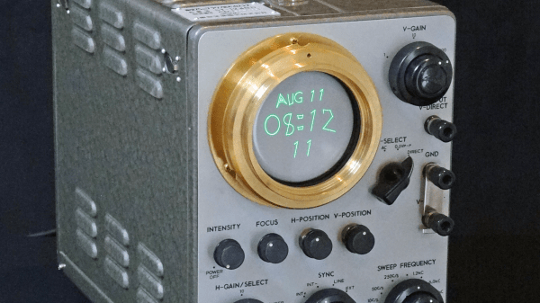
[Aaron]’s client was setting up a Metropolis themed man-cave and commissioned him to build a Metropolis Oscilloclock which would not only show the 24 hour and 10 hour clocks from the film, but also accurately reproduce the clock movements and its fonts. [Aaron]’s Oscilloclock is his latest project in the series of bespoke CRT clocks which he has been building since he was a teen.

The clock is built around a Toshiba ST-1248D vintage oscilloscope that has been beautifully restored. There are some modern additions – such as LED glow indicators for the various valves and an external X-Y input to allow rendering Lissajous figures on the CRT. He’s also added some animations derived from the original poster of the film. Doing a project of this magnitude is not trivial and its taken him almost eight months to bring it from concept to reality. We recommend looking through some of his other blog posts too, where he describes how oscilloclocks work, how he builds the HV power supplies needed to drive the CRT’s, and how he ensures vibration and noise damping for the cooling fans used for the HV power supplies. It’s this attention to detail which results in such well-built clocks. Check out some of [Aaron]’s other awesome Oscilloclock builds that we have featured over the years.

The film itself has undergone several restoration attempts, with most of it being recovered from prints which were discovered in old archives. If you wish to go down that rabbit hole, check out Wikipedia for more details and then head over to YouTube where several versions appear to be hosted.

Continue reading “Decimal Oscilloclock Harks Back To 1927 Movie”

Homemade Subaru Head Unit Is Hidden Masterpiece

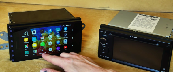
The Subaru BRZ (also produced for Toyota as the GT86) is a snappy sportster but [megahercas6]’s old US version had many navigation and entertainment system features which weren’t useful or wouldn’t work in his native Lithuania. He could have swapped out the built in screen for a large 4G Android tablet/phone, but there’s limited adventure in that. Instead, he went ahead and built his own homemade Navigation system by designing and integrating a whole bunch of hardware modules resulting in one “hack” of an upgrade.

The system is built around a Lenovo 4G phone-tablet running android and supporting GPS, GLONASS as well as the Chinese BeiDou satellite navigation systems. He removed the original daughter board handling the USB OTG connection on the tablet, and replaced it with his version so he could connect it to his external USB board via a flat ribbon cable. The USB board contains a Cypress 4-port USB hub. One port is used as the USB HID device to allow external buttons for system control — Power, Volume Up/Down, Fwd/Rev, Play/Pause, and Phone Answer/Hangup. The second port is used as a regular USB input to allow connecting external devices such as flash drives. The third one goes to a reversing camera while the fourth port goes to a USB DAC.

The USB DAC is another hardware board by itself and also includes a Bluetooth module which integrates his phone’s audio and control functions with the on-board system. There’s also an audio mixer which allows him to use the phone audio without having to miss out on the navigation prompts from the tablet. Both boards also contain several peripheral circuits such as amplifiers and DC power supplies. Audio to the speakers is routed through six LM3886 based power amplifier boards. And the GPS module receives its own special low-noise amplifier board to ensure extremely strong reception at all times. That’s a total of ten boards custom built for this project. He’s also managed to source all the original harness connectors so his system is literally a snap in replacement. The final assembly looks pretty dashing.

For some strange reason, the Lenovo tablet uses 4.35V as the ‘fully charged” value for its LiPo instead of the more common 4.20V, so even with the whole system connected to a hefty 12V lead acid battery from which he’s deriving the 4.20V charging voltage for the tablet, it still complains about “low battery” — and he’s looking for advice on how he can resolve that issue short of blowing up the LiPo by using the higher charge voltage. Besides that, he’s (obviously a kickass) hardware designer and a little bit rusty on the software and programming side of things, for which he’s looking for inputs from the community. His introductory video is almost 30 minutes long, but the shorter demo video after the break shows the system after installation in his car. He’s posted all of his Altium hardware source files on the project page, but until he shares PDF versions, it would be difficult for most of us to look at his work.

Continue reading “Homemade Subaru Head Unit Is Hidden Masterpiece”