Simple Superheterodyne SW Receiver Harks Back Almost 100 Years

Early radio receivers worked on a principle called Tuned Radio frequency (TRF), patented in 1916. They weren’t very easy to use, requiring each stage to be tuned to the same frequency (until ganged capacitors made that a bit easy). The Superheterodyne design, devised in 1918, was superior, but more expensive at that time. Cost considerations led adoption of the Superhet design to lag behind TRF until almost 1930. Since then, until quite recently, the Superhet design has been at the heart of a majority of commercial radio receivers. Direct Conversion Receivers were devised around 1930, but required elaborate phase locked loops which restricted their use in commercial receivers. The point of all this background is that the Superhet design has served very well for more than 90 years, but will soon be rendered redundant once Software defined Radio (SDR) becomes ubiquitous. Which is why this study of the simple Superheterodyne shortwave receiver deserves closer study.

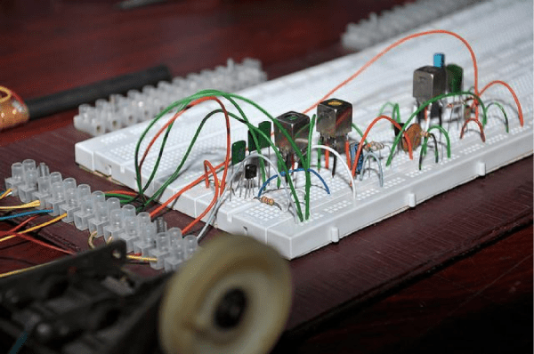
[Dilshan] built this two transistor and two IF transformer based superheterodyne radio designed to receive 13m to 41m bands. The whole build is assembled on a breadboard, making it easy to teach others to experiment. [Dilshan] offers very useful insights into antenna, rod coil and IF transformer parameters. To dive in to Radio architecture, check this post on Amateur Radio. And if you would like to get a closer look at Antique Radios, check this post on Restoring Antique Radios.

Penny And Paper Clip Heat Sinks

A bunch of audio heads over at the Head-Fi forum were discussing handy and quick heat sinking methods, leading to much speculation and conjecture. This finally prompted [tangentsoft] to take matters in his own hands and run some tests on DIY Heat Sinks.

The question that sparked this debate was if a paper clip is a good enough heat sink to be used for a TO220 package. Some folks suggested copper pennies (old ones minted 1981 and earlier – the new ones are zinc with copper plating and won’t help much). [tangentsoft] built a jig to test six LM317 regulators in constant current mode set to 0.125A and 2w dissipation. The six configurations were a paper clip, a single penny bolted to the regulator, a regular Aavid TO220 heat sink, a set of 4 pennies bolted, a single penny epoxy glued and finally a single penny soldered directly to the regulator.

The results were pretty interesting. The paper clip scored better than any of the single pennies! The quad-penny and the Aavid heat sink fared above all the other configurations, and almost at par with each other. [tangentsoft] posts his review of each configurations performance and also provides details of his test method, in case someone else wants to replicate his tests to corroborate the results. He tested each configuration independently for one hour, gathering just over 10000 readings for each setup. Other nearby heat sources were turned off, and he placed strategic barriers around the test circuit to isolate it from the effects of other cooling / heating sources. He even removed himself from the test area and monitored his data logging remotely from another room. When he noticed a couple of suspect deviations, he restarted the test.

[tangentsoft] put all the data through Mathematica and plotted his results for analysis, available at this link [pdf, 2.8MB]. So the next time you want to heat sink a regulator for cheap, just hunt for Clippy in your box of office supplies. Do remember that these methods will work for only a couple of watts dissipation. If you would like to cast and build your own heat sinks out of aluminum, check out this post about DIY Aluminum heat sink casting. And if you need help calculating heat sink parameters, jump to 12:00 minutes in this video from [Dave]’s EEVBlog episode on Dummy loads and heat sinks.

Thanks to [Greg] for sending in this tip.

Looking Inside The KR580VM80A Soviet I8080 Clone

The folks at Zeptobars are on a roll, sometimes looking deep inside historic chips and at others exposing fake devices for our benefit. Behind all of those amazing die shots are hundreds of hours of hard work. [Mikhail] from Zeptobars recently tipped us off on the phenomenal work done by engineer [Vslav] who spent over 1000 hours reverse engineering the Soviet KR580VM80A – one of the most popular micro-controllers of the era and a direct clone of the i8080.

But before [Vslav] could get down to creating the schematic and Verilog model, the chip needed to be de-capped and etched. As they etched down, they created a series of high resolution images of the die. At the end of that process, they were able to determine that the chip had exactly 4758 transistors (contrary to rumors of 6000 or 4500). With the images done, they were able to annotate the various parts of the die, create a Verilog model and the schematic. A tough compatibility test confirmed the veracity of their Verilog model. All of the source data is available via a (CC-BY-3.0) license from their website. If this looks interesting, do check out some of their work that we have featured earlier like comparing real and fake Nordic dies and amazing descriptions of how they figure out the workings of these decapped chips. If this is too deep for you check out the slightly simpler but equally awesome process of delayering PCBs.

Cheap, Dirty And Perfect V-Groove Foam Cutter

If the only tool you have is a hammer, everything looks like a nail. Conversely, if you have the right tool for every job, it makes the difference between pro and amateur. [ftregan] needs to cut perfect V-grooves in foam for many of his projects, especially building RC planes. He wasn’t too satisfied with the results using his Xacto knife. And a proper tool was going to set him back by almost $25, but following that example he built his own version of the tool for much less.

Two pieces of wood cut at a 45 degree angle are held between two flat support pieces. A pair of regular shaving blades form the cutting elements. While it looks simple, it’s important to get the angles and blade directions correct. A central wooden wedge holds the two blades in place. He also added a small guide marker that let’s you cut precise straight grooves. [ftregan] built the tool to allow cutting 6mm thick foam but given that it’s so quick and cheap to build, we guess it’s easy to make a few of these to allow cutting different thicknesses of foam. We’re sure that many of you will find different or better ways of doing this, but considering [ftregan] spent just 15 minutes cooking this up, it’s not too bad, especially since the results are mighty good.

Another method of cutting foam is with hot wire. Check out this DIY Foam Cutter that we featured earlier.

Nixie Inspired 7 Segment Display

The supply of Nixie tubes from east European stock piles is still enough to keep their prices down. But once those start dwindling, prices will move north. Besides, if you want to use them, you need to work with high voltage supplies and worry about not getting zapped while trying to debug a circuit. [FilleK] had some time to spare and decided to build a cheaper substitute for a real nixie tube using a regular 7 segment LED display.

We have already seen this hack before, in the Arduino-based ENIGMA replica. But [FilleK] improved on that by adding an extra LED to simulate the radiant glow typical of Nixie tubes. His project log describes the fairly straightforward process using parts that can be found easily. A piece of plastic, painted in a shade of copper and fixed around the 7 segment display, acts as a nice baffle to contain and reflect the ambient glow of the back-light LED. A nice improvement would be to add a random flicker to the background LED. Maybe add an Octal socket (the decimal point had to be nixed though!), and cap it in a proper glass tube. If you’d rather work with the real McCoy, check out our archives.

Automated Pocky Dispenser

Sometimes, along comes a build project that is not so much a fail, as how not to do it. First off, some of us here had to look up what a Pocky is, never having heard, seen or tasted one – seriously. Once satisfied, we turned our attention to [Michael]’s Automated Pocky Dispenser. Took a while for us to figure out if it’s useful or not. But it’s a fun, quick project that [Michael] put together in around an hour using parts lying around in his office.

For those of you who’d like to know, a Pocky is a chocolate-coated biscuit stick, although you can also buy it in other flavors. You can grab one from a box, but maybe it tastes better when you dispense it by banging a big red button. [Michael] says he used  incredibly advanced construction techniques, but we leave it to our readers to decide on that. The key element of the build is the special “flexible coupling” that he built to transfer the rotation of the stepper motor to the dispensing mechanism. The rest of the build consists of an Arduino, stepper motor, driver, and giant red button. Special motor driving code ensures that the dispenser wiggles back and forth every time, preventing any stuck Pocky’s. And the Electronics are, well, hanging out for all to see. Happy with the success of his build, [Michael] is planning an upgraded version – to connect the Pocky Dispenser to the cloud for statistical gathering of office Pocky habits. He claims even Google does not have that data. To see the dispenser in action, check out the video below.

Continue reading “Automated Pocky Dispenser”

Putting Oculus Rift On A Robot

Many of the early applications for the much anticipated Oculus Rift VR rig have been in gaming. But it’s interesting to see some more useful applications besides gaming, before it’s commercial release sometime this year. [JoLau] at the Institute i4Ds of FHNW School of Engineering wanted to go a step beyond rendering virtual worlds. So he built the Intuitive Rift Explorer a.k.a IRE. The IRE is a moving reality system consisting of a gimbaled stereo-vision camera rig transmitting video to the Rift, and matching head movements received from the Oculus Rift. The vision platform is mounted on a Remote-controlled robot which is completely wireless.

One of the big challenges with using VR headsets is lag, causing motion sickness in some cases. He had to tackle the problem of latency – reducing the time from moving the head to getting a matching image on the headset – Oculus Rift team specified it should be less than 20ms. The other important requirement is a high frame rate, in this case 60 frames per second. [JoLau] succeeded in overcoming most of the problems, although in conclusion he does mention a couple of enhancements that he would like to add, given more time.

[JoLau] provides a detailed description of the various sub-systems that make up IRE – the Stereo camera,  audio and video transmission, media processing, servo driven gimbal for the stereo camera,  and control system code. [JoLau]’s reasoning on some of the interesting hardware choices for several components used in the project makes for interesting reading. Watch a video of the IRE in action below.

Continue reading “Putting Oculus Rift On A Robot”