Custom Controller Makes Turbomolecular Pump Suck

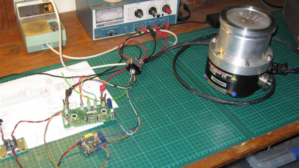
[Mark Aren] purchased a pair of Turbomolecular pumps (TMP) sans controllers, and then built an FPGA based BLDC controller for the Turbomolecular pumps. A TMP is similar to a jet turbine, consisting of several stages of alternating moving turbine blades and stationary stator blades, and having turbine rotation speeds ranging from 10,000 rpm to 90,000 rpm. TMP’s cannot exhaust directly to atmosphere, and must be combined with a backing (or roughing) pump to create a lower grade vacuum first. They find use in lots of applications such as electron microscopy, analytical sciences, semiconductors and lamp manufacturing. With the lamp industry rapidly embracing LEDs, many of the traditional lamp making lines are getting decommissioned, and if you are lucky, you can snag a TMP at a low cost – but it still will not be cheap by any means.

The two BOC-Edwards EXT255H Compound Molecular Pumps (PDF), that [Mark] bought did not have their accompanying EXC100E Turbomolecular Pump Controllers (PDF), and given pandemic related restrictions, he decided to build a controller of his own, using components and modules from his parts bin. The pump and controller user manuals offered only sketchy details about the sensored BLDC motor used in the pump. The low phase-to-phase resistance implied low drive voltage, and [Mark] decided to try running it at 24 V to start with. He already had experience using the Mitsubishi PS21245-E IGBT inverter bridge, and even though it was rated for much higher voltages, he knew that it would work just fine at 24 V too.

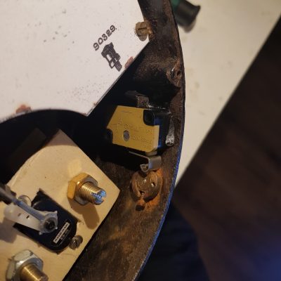
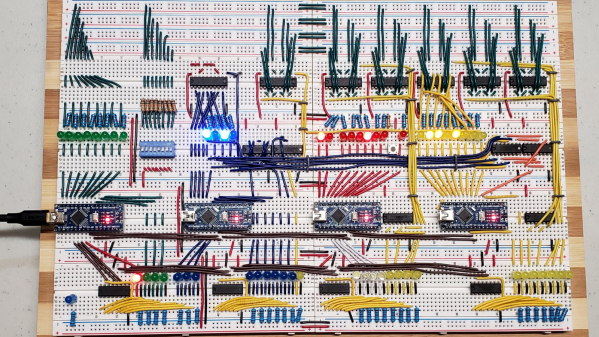
After figuring out a state machine for motor commutation that utilized PWM based adjustable current control, he implemented it on a 128 element FPGA board. Considering how expensive the TMP was, he wisely decided to first try out his driver on a smaller “expendable” BLDC motor. This whole process was non-trivial, since his available IGBT module was untested and undocumented, and required several tweaks before he could run it at the required 12 kHz PWM signals. His test motor was also undocumented, failing to run correctly when first hooked up. Fixing that issue meant having to disassemble the motor to check its internal wiring. Eventually, his efforts paid off, and he was able to safely run the TMP motor to confirm that his design worked.

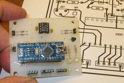
With FPGA code, IGBT wiring and power supply issues sorted, the next step was to add a supervisory micro-controller, using an Arduino Nano. Its functions included interfacing with a touch screen LCD as a user interface, communicating with the FPGA module, and controlling several relays to switch power to the motor power supply, the roughing pump, TMP cooling fan, and a solenoid for the vacuum vent. Spindle current is calculated by measuring voltage drop across shunt resistors on the low side of the IGBT. Motor speed is measured using one of the motor hall sensors, and a thermistor provides motor temperature sensing. [Mark]’s PCB fabrication technique seems a bit different too. Using an Excellon drill file, he drills holes in a piece of plastic using a laser cutter to create a bare board, and then solders copper tracks by hand.

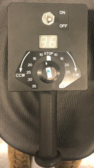
His initial tests at atmospheric pressure (although not recommended unless you monitor pump temperature), resulted in 7300 rpm while consuming about 7 Amps before he had to shut it down. In further tests, after adding a roughing pump to the test setup, he was able to spin the TMP to 20,000 rpm while it consumed 0.6 A. Obviously, the pump is rated to operate at a higher voltage, possibly 48 V based on the values mentioned in the TMP controller manual. The project is still “work in progress” as [Mark] hopes to eventually drive the pump up to its specified 60,000 rpm operating speed. What is not clear is what he eventually intends to do with this piece of exotic machinery. All he mentions is that “he has recently taken an interest in high-vacuum systems and is interested in exploring the high-vacuum world of electron guns.”

Maybe [Mark] can compare notes with the Open Source Turbomolecular Pump Controller that we featured some time back. And if you’d like to be a little bit more adventurous and build you own TMP, we got you covered with this DIY Everyman’s Turbomolecular Pump.

Uncommon Bárány Chair Gets Fixed Up

Ever heard of a Bárány chair? Neither had [Troy Denton] before he was asked to repair one, but that didn’t stop him from rolling up his sleeves and tying to get the non-functional device back in working order. As it didn’t come with a user guide, manual, schematic or any other information, he had to rely on his experience and acumen gathered over years of practical work. Luckily for us, he decided to document the whole process.

While it’s not well known outside of aviation circles, the Bárány chair is an important piece of equipment in training pilots to get used to spatial disorientation. The device is essentially a motorized revolving chair, the idea being to spin the subject to induce disorientation. Rotation speed and direction can be controlled via a handheld wireless remote terminal.

When [Troy] first powered it up, the error code on the remote indicated “no power to base unit”. That turned out to be a quick fix – he simply had to move the power connection from a switched socket that had been turned off to a different outlet. But while that cleared the error message, the chair still wouldn’t rotate for any of the knob settings.

Manually rotating the chair showed the RPM on the remote, so [Troy] narrowed down his search to the motor related sections. The motor was being driven by a servo type signal, but changing the speed and direction knob on the remote didn’t seem to alter the control signal when he checked it with his scope. Opening up the hand held remote immediately uncovered the failed part – the rotary encoder for setting the speed and direction had physically split in to two pieces.

Since there was a clean split in the encoder, he was able to temporarily hold it back together to confirm that the chair could spin up. The cause was most likely “User Error” – the last person to conduct the test probably turned the knob rather enthusiastically. A new part is on the way, and the chair should be getting back to making prospective pilots dizzy in no time.

We love a good repair story here at Hackaday. Whether it’s patiently rebuilding a snapped PCB with bodge wires or coming up with replacement parts that may well be better than the originals, we never get tired of seeing a broken piece of gear put back together.

Continue reading “Uncommon Bárány Chair Gets Fixed Up”

Vintage Meters Reborn As Steam Punk Clock

[Build Comics], purveyors of comic strips “where tools are heroes”, have saved another pair of old, vintage, analog meters from the junkyard by converting them into a Meter Clock. The real heroes of the story are their trusty tools – Mac X the knife, Mr. TS the table saw and his trusty band of clamps, G. Rinder the angle grinder, Weldy the welder, Sharp Eye the marker, rounded up by Sandy the Sander and Jiggy Saw. The Drake & Gorham (London) meters going under the knife appear similar to vintage hardware from just after the end of World War II, such as this Ferranti Ammeter found at the Science Museum Group, making them at least 75 years old.

A small cam is used to engage the DST switch.

As you might expect, the conversion process is reminiscent of their previous projects. The original moving-coil movements are discarded, and the pointer is attached to a servo which will act as the new movement. Fresh dials are prepared to replace the original ampere markings with hours and minutes. To retain some of the original charm, the new dials have discoloration and blemishes replicated from the old dials.

The set screw which was once used to align the pointer with the zero mark on the dial is now used to activate a micro switch that enables daylight savings time. Two additional buttons provide a convenient interface to adjust the time. Precision time signals are derived from a DS3231 RTC module connected to an Arduino. A pair of seven segment displays are connected to the Arduino to make it easier to set the time. A piece of oak plank, surrounded by a metal angled frame, is used as a base for mounting the two meters so that the clock can be hung up on the wall.

If you’d like to build some more vintage inspired instrumentation, [Build Comics] have you covered with a Classy Weather Display or a Plant Moisture Gauge.

Continue reading “Vintage Meters Reborn As Steam Punk Clock”

Build An 8-bit CPU To Know “But How Do It Know?”

Sometime around 2009, [J. Clark Scott] published a book aimed to demystify computers for everyone by walking through construction of an 8-bit CPU from scratch. The book had a catchy, but somewhat confusing title But How Do It Know?. The back story on the title goes something like this: Joe is a very nice fellow, but has always been a little slow. He goes into a store where a salesman is standing on a soapbox in front of a group of people. The salesman is pitching the miracle new invention, the Thermos bottle. He is saying, “It keeps hot food hot, and cold food cold….” Joe thinks about this a minute, amazed by this new invention that is able to make a decision about which of two different things it is supposed to do depending on what kind of food you put in it. He can’t contain his curiosity, he is jumping up and down, waving his arm in the air, saying “but, but, but, but…” Finally he blurts out his burning question “But how do it know?” Joe looked at what this Thermos bottle could do, and decided that it must be capable of sensing something about its contents, and then performing a heating or cooling operation accordingly. Joe’s concept of how the bottle worked was far more complicated than the truth. With that introductory opening, [J. Clark Scott] goes on to cover basic number theory, leading on to logic gates, and finally the 8-bit CPU.

[Patrick LeBoutillier] decided to build a hardware version of the CPU/computer as described in [John Clark Scott]’s book. In order to keep size and cost within reasonable bounds, he choose a hybrid construction using a combination of micro-controllers and SN74HC logic IC’s. When used as a companion project alongside reading the book, he hopes people can get their hands dirty and try it out for themselves. He has published a series of 14 videos covering construction of the CPU and the first Introductory video is embedded after the break below. For the micro-controller part of the project, he is using four Arduino Nanos, the code and install instructions for which are available at his Git repo. The Fritzing schematic, also available at the repo, might look a bit daunting at first look, but when you follow along his video series, it becomes easier. You can preview the first three chapters of the book at the “But How Do It Know?” website.

If FPGA’s are more of a thing for you, or you’d like to dip your feet learning FPGA, then [Patrick] has another series of 17 videos (embedded below) where he goes through the same process using a Digilent BASYS3 FPGA development board. These aren’t your only options — if you just want to understand how it works, without having to build the hardware, then check out the online, browser based implementation of the [Clark Scott] CPU.

If it seems the breadboard build of this 8-bit CPU looks complex, then this
Home Made 8-bit CPU Is A Wiry Blinky Build and a veritable rats nest of jumper wires.

Continue reading “Build An 8-bit CPU To Know “But How Do It Know?””

Simple Christmas Tree Christmas Tree Ornament

When the only tool you have is a hammer, every problem looks like a nail. An LED ornament for the Christmas tree can be built in any manner of simple, easy implementations. You certainly don’t need an ARM Cortex M4 CPU running at 120MHz having a mouthful of three letter features like FPU, ETM, ETB, ECC, RWW, TCM, EIC, AES, CAN bus and much, much more. But [Martin Held] built a super simple LED Christmas tree ornament using the ATSAME51 series micro-controller, which he regularly works with and had on hand, and lots of bi-color LEDs. He already had schematic symbols and programmers for the device from other projects where he uses it more extensively, so putting it all together in time for the festive season was that much faster for him, despite the fact that the micro-controller was most likely the cheapest part of the BOM, besides the passives.

At this point it might be tempting to argue that it would have been so much simpler to use addressable LED’s, such as the WS2812B or the APA102C. You can drive them using a more basic micro-controller, and not require so many GPIO pins. But using such “smart pixel” LED’s for hand assembled prototypes can sometimes lead to unexpected results. If they are not stored in sealed tape/reel form, then storage conditions can have an adverse effect leading to dead pixels. And, they need a specific baking procedure before being soldered. Doing that for a few LEDs at home can be tricky.

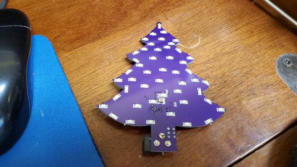
So for the LED’s, he again went a bit off the beaten path, selecting to use three different color styles of bi-color LED’s with easy to hand-solder, 1206 footprints. This allows him to get a fairly random mix of colors in the completed ornament.

The LED array is pseudo-charlieplexed. One terminal of each LED goes to a GPIO pin on the micro-controller and the other terminal of all the LED’s are connected to a single complimentary pair of N-channel/P-channel MOSFETs — connected in totem-pole fashion. Depending on which MOSFET is switched on via a GPIO pin driving the gate pin high or low, the second terminal of each LED gets connected to either supply or ground. In combination with the GPIO pins being driven high/low, this allows the bi-color LED to be biased in either direction. Getting each LED to emit one color is simple enough — setting all LED GPIOs low, and MOSFET gate GPIO high will bias the LEDs in one direction. Reverse the GPIO logic, and the LEDs will be biased in the other direction. If this is done slow enough, the two colors can be differentiated easily. If the driving logic is made fast, changing states every 10us, the two separate colors merge to form a third hue. With some clever bit of code, he also adds some randomness in the GPIO output states, resulting in a more appealing twinkling effect. [Martin] does a detailed walk through in the video embedded below.

If you have the same bunch of parts lying around and wish to replicate the project, be warned that the KiCad source files will need some work to clean up errors — [Martin] was in a hurry and knew what he was doing so there are some intentional mistakes in the schematic such as using the same symbol for the N-channel and P-channel MOSFETs, and uni-directional LED symbol in place of the bi-directional one. And for programming, you will need one of these pricey pogo-pin style cables, unless you decide to edit the PCB before sending off the Gerbers.

[Martin] built just three of these bespoke ornaments, retaining one and giving away the other two to a neighbour and a co-worker. But if you would really like to build a tree ornament with addressable LEDs, then check out the Sierpinski Christmas Tree which can be cascaded to form an array of tree ornaments.

Continue reading “Simple Christmas Tree Christmas Tree Ornament”

DIY Injection Molding Press

While 3D printing has now become easily accessible and cheap, there are still several use cases where you need the advantages offered by injection molding, even for small batch runs. Professional small-batch injection molding can be pretty expensive, and buying a manual machine can cost quite a bit. Of course, there are a number of DIY injection molding projects to choose from, but they usually involve a fair amount of tools and labour. [Bolzbrain] wanted to bypass all of the heavy cutting, welding and frame assembly work, so he’s built himself a DIY Injection Molding Press for cheap using an off the shelf, six ton hydraulic press. At final count, he ended up spending about €150 for the machine and another €120 for tools to build the machine. He also managed to locate a cheap, local CNC service that gave him a good deal on machining the Dies. But of course you can’t put a price on the lessons learnt and the satisfaction of having built it by hand.

Choosing the hydraulic press is a great idea as it provides the high pressure needed for the job without the operator having to exert a lot of effort, which is a big drawback with some of the other DIY machines. As a bonus, the structural frame is quite sturdy and well suited for this purpose. The other main part of such a machine is the heated injection block and there are several different ways of doing it. After some amount of studying probable solutions, he decided to build a heated aluminium block through which the plastic granules can be rammed using the hydraulic piston. Heating is provided by a pair of 500W heaters and a type ‘k’ thermocouple does temperature sensing. An industrial PID controller adjusts the block temperature via a solid state relay. Overall, the electrical and mechanical layout cannot get any simpler.

[Bolzbrain] did a great job of documenting his build over a series of videos and more wizened hackers watching them will squirm in their seats spotting the numerous fails. He bought the cheapest pedestal drill machine that he could buy and watching the drill struggle while making a 26mm hole in the aluminium block is quite jarring.

The electrical wiring has a lot of scope for improvement – with 220V AC heaters, exposed wiring and jury rigged panel held up with a pair of clamps. Installing and removing the die is a task and requires a lot of fiddling with several C-clamps — something which needs to be repeated for every shot. Maybe toggle clamps could help him to ease die fixing and removal. Once he figures out about mold release agents and wall draft angles, he won’t have to struggle trying to remove the molded article from the die. Then there’s the issue of proper runner design so that the thermo-plastic can quickly fill the mold cavity completely without any pockets.

But in the end, all that matters is that he is getting reasonably good molded parts for his purposes. With more tweaking and incremental improvements, we’re sure he’ll get better results. The video after the break is a short overview of his build, but the project page has a series of detailed videos covering all aspects of the project. And if you’d like to get an introduction to desktop injection molding, check out “Benchtop Injection Molding for the Home Gamer

Continue reading “DIY Injection Molding Press”

Amazon Halo Teardown Is Supremely Thorough

We rarely see teardowns this detailed. [txyzinfo] wanted to know what hardware was under the hood, and did an amazing Amazon Halo Teardown.

Sometime around the middle of 2020, Amazon jumped on to the health and fitness tracker space with the introduction of the Halo — a $100 device with an add on $4 monthly subscription service if you wanted additional features, which Amazon calls “labs”, many of which are third-party services. The device does not have any display at all, and any metrics that need to be displayed (heart rate, steps, calories, etc.) show up on the Halo phone app. Halo’s focus is more on health, rather than fitness. It helps monitor your active and sleep states, keeps track of body fat, and reports your emotional state.

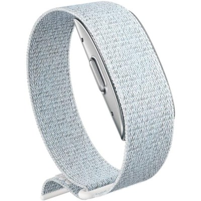
We won’t delve much in to the pros and cons of the device, other than mention two features which have the potential to creep out most folks. The device has a pair of microphones, which listen to the “tone” of your voice and report on your emotional state. The other is its use of your phone via the companion app, to take photos of you, preferably dressed in your undergarments. Your front, back and side photos get uploaded to Amazon servers, get converted to a 3D model, and then downloaded back to your phone. Amazon mentions that the photos are never retained and deleted from their servers once your 3D model is transferred back to the phone. Amazon’s ML algorithms then calculate your body fat percentage. More worryingly, the app offers a slider which you can move to see how you will “look” if you have higher or lower body fat percentages.

Fortunately for us hardware hacker types, [txyzinfo] wanted to unlock all the secrets Amazon poured into this design. Even if the device in particular does not interest you, the techniques he uses are very educational and will prove a useful addition to your skills. The device does not have any external fasteners, with the back cover being held together with glue. [txyzinfo] starts off by applying a solvent around the back cover to soften the glue, then works with his spudger to pry it open. The back cover appears to have an antenna with touch-contact terminations without a connector. The main body holds the rest of the electronics, and can be easily removed by unscrewing the four corner screws. Using a combination of solvent to soften the glue at various points, and snips to cut off retaining plastic tabs, he manages to untangle the hybrid rigid-flex PCB assembly from its plastic-metal clam-shell.

He uses a hot-air blower to cleanly separate the flex PCB parts attached to the rigid PCB. With all the flex pieces removed, he is left with the main part of the device — the rigid PCB with most parts potted under a metal shield filled with what appears to be a soft, grey compound. At this point, we are not sure if the potting compound is for heat dissipation, or just to obfuscate reverse engineering. His next action gives us a severe case of the heebie jeebies, as he clamps the PCB to a milling machine, and mills away the sides of the metal shield. Next, he heats the whole assembly with the hot air gun to melt all the solder, applying some generous amounts of flux, using the spudger to pull apart the PCB from the components embedded in the potting compound. Check out the video after the break to see his tear down techniques in action.

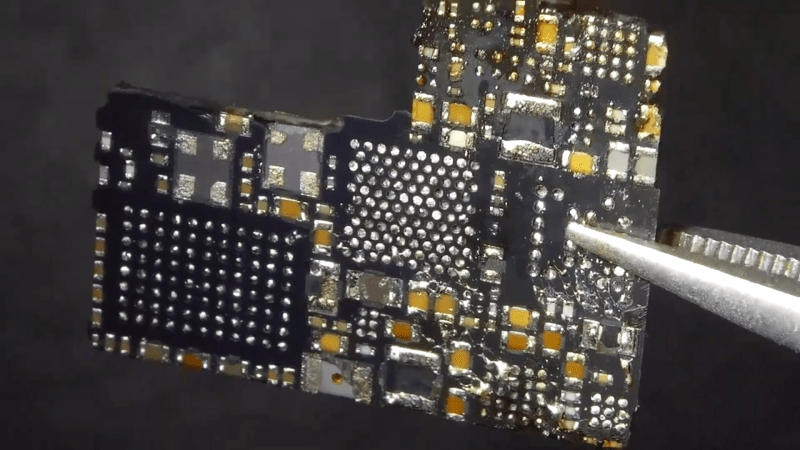
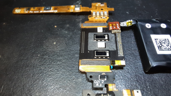
His plan was to identify as many parts as he could, but he wasn’t very successful, and managed to identify just a few — the two MEMS microphones, two temperature sensors and the LED driver on the flex PCB, and the photo-diodes, 6-axis IMU, battery charger and flash memory on the main board. The board has an uncommon 5-layer stack up, with the centre layer being ground. PCB de-layering is a time consuming process and requires a lot of patience, but in the end, he was able to get a pretty good result. He found some oddities in the track layout and was able to identify some of the more common connections to the I2C bus and between the micro-controller and its memory. He also located several test points which seem promising for a second round of investigations. Sometime in the future, he plans to get another Halo and have a go at it using the JTAGulator and GoodFET.

Tear downs are a favourite for all hackers, as is evident by the regularity with which we keep seeing them. If this one hasn’t whetted your appetite, then check out this other Fitness Tracker Teardown which is a lesson in Design for Manufacture.

Continue reading “Amazon Halo Teardown Is Supremely Thorough”