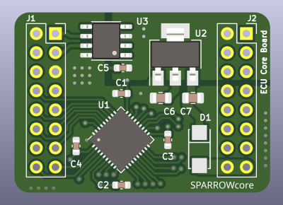
A graph from the article, showing dead zones and error bars for the ESP32 ADC

RP2040, ESP32, And An Atmega Have An ADC-Off

[Simon Monk] got frustrated with bad ADC performance when tinkering with an ESP32 board, and decided to put three of the nowadays-iconic boards to the test – a classic ESP32 devboard, a Pi Pico with an RP2040, and an Arduino Uno R3 with an ATmega328P. To do that, he took a bench PSU, added a filter circuit to it, went through the entire ADC range for each board, took a large number of samples at different points and plotted the results. The plots show us both linearity and precision, as well as ADC dead zones, and the results are quite surprising.

The ESP32 doesn’t only have the most limited ADC with maximum 1V input, it also produces the worst results out of all three, with large error bars and sizeable dead zones at both ends. The Pi Pico, despite being colloquially known for its subpar ADC, produces better results than the ESP32. However, both of them are dwarfed by the ATMega328P’s performance. If you need a dedicated ADC, it might just be a good idea to put an ATMega328P on your board.

The example code is provided, and we are wondering whether there are methodology errors. For instance, the ATMega328P code is written in Arduino-supplied C++, but ESP32 and RP2040 in particular used MicroPython, which does more than just running the code, and MicroPython for ESP32 in particular creates a WiFi access point – something known to induce noise into ADC readings. Nevertheless, this is a fun comparison, and we like when hackers do microcontroller standoffs like that – for instance, check out this review from 2017 which pits a dozen microcontrollers of the time against each other!

Probes connected from a Pi Pico board to the SPI flash chip, with other end of the probes connected tot the level shifter circuit resistors

Motherboard Revived With Simplest 1.8V SPI Shifter Ever

If you have ever had to fix a modern desktop motherboard, you might have noticed that the BIOS (UEFI) SPI flash is 1.8V – which means you can no longer use a Raspberry Pi or a CH341 adapter directly, and you’d need to use a 1.8V level shifter of some sort. Now, some of us can wait for a 1.8V level shifter adapter from an online store of your choosing, but [treble] got a “BIOS flash failed” motherboard from Facebook Marketplace, and decided to make it work immediately.

She tells us a story about reviving the motherboard, and there’s one thing she shows that is interesting in particular – a very simple way to level shift 3.3V signals from a serprog-flashed Pi Pico down to the 1.8V that the flash chip required, something you are guaranteed to be able to build out of the parts in your parts bin, only requiring nine resistors and an NPN transistor. If you ever need to reflash BIOS on a modern motherboard, take note. As for 1.8V rail, she ended up tapping the 1.8V power pin of the SPI chip the motherboard itself to power the chip while programming it.

In the end, after swapping the two BIOS chips places and fixing a broken trace mishap, the motherboard booted, and works wonderfully to this day, a much-needed upgrade to [treble]’s toolkit that allows her to do RISC-V cross-compiling with ease nowadays. This is not the first time we see people reflash modern boards with 1.8V chips – if you want to learn more, check out this incredibly detailed writeup! Need to do some further debugging? Use your Pico as a POST card!

Ethernet For Hackers: Transformers, MACs And PHYs

We’ve talked about Ethernet basics, and we’ve talked about equipment you will find with Ethernet. However, that’s obviously not all – you also need to know how to add Ethernet to your board and to your microcontroller. Such low-level details are harder to learn casually than the things we talked about previously, but today, we’re going to pick up the slack.

You might also have some very fair questions. What are the black blocks near Ethernet sockets that you generally will see on boards, and why do they look like nothing else you see on circuit boards ever? Why do some boards, like the Raspberry Pi, lack them altogether? What kind of chip do you need if you want to add Ethernet support to a microcontroller, and what might you need if your microcontroller claims to support Ethernet? Let’s talk.

Transformers Make The Data World Turn

One of the Ethernet’s many features is that it’s resilient, and easy to throw around. It’s also galvanically isolated, which meansĀ  you don’t need a ground connection for a link either – not until you want a shield due to imposed interference, at which point, it might be that you’re pulling cable inside industrial machinery. There are a few tricks to Ethernet, and one such fundamental Ethernet trick is transformers, known as “magnetics” in Ethernet context.

Each pair has to be put through a transformer for the Ethernet port to work properly, as a rule. That’s the black epoxy-covered block you will inevitably see near an Ethernet port in your device. There are two places on the board as far as Ethernet goes – before the transformer, and after the transformer, and they’re treated differently. After the transformer, Ethernet is significantly more resilient to things like ground potential differences, which is how you can wire up two random computers with Ethernet and not even think about things like common mode bias or ground loops, things we must account for in audio, or digital interfaces that haven’t yet gone optical somehow.

Continue reading “Ethernet For Hackers: Transformers, MACs And PHYs”

A bias tee module added inside the Starlink terminal, connected to the pads where a GPS antenna used to be wired

GPS Antenna Mods Make Starlink Terminal Immune To Jammers

The Starlink receivers need positioning and precise timing information to function, and currently the best way to get that information is to use a global navigation satellite system (GNSS) such as GPS. Unfortunately, the antenna used for this secondary satellite connection leaves something to be desired. Of course, when it comes to solving Starlink problems, there’s no one best than [Oleg Kutkov], whose duty is to fix and improve upon Starlink terminals used in Ukraine — and when the specific problem is GPS bands getting jammed by the invading military, you better believe that a fix is due.

[Oleg] sets the scene, walking us through the evolution of GPS circuitry on the Starlink terminals. Then he shows us the simplest mods you can do, like soldering an improved passive antenna in place of the chip antenna currently being used. Then, he takes it up a notch, and shows us how you could attach an active antenna by using a bias tee module, a mod that would surely work wonders on more than just this device! Then, he brings out the test result tables — and the differences are impressive, in that the Starlink terminals with active antenna mods were able to get GPS signal in areas with active jamming going on, while the unmodified ones could not.

The post is exceptionally accessible, and a must read for anyone wondering about GPS antenna reception problems in customer-accessible devices. This is not the only Starlink hardware mod we’ve seen [Oleg] make, we’ve just covered his Starlink Ethernet port restoration journey that meticulously fixes Ethernet connectivity oversights in the newer models, and the blog also has an article about powering Starlink terminals without the need for PoE, so, do check it out if you’re looking for more!

A screenshot of the drone monitoring application, showing spoofed drones and their coordinates

Can’t Disable DJI Drone ID? Spoof It With An ESP!

We have been alerted to a fun tool, a DJI DroneID spoofer software for ESP8266/ESP32 and some other popular MCUs. Last year, we’ve told you about DJI DroneID — a technology DJI added to their drones, which broadcasts data including the drone operator’s GPS position, which, in turn, appears to have resulted in Ukrainian casualties in the Ukraine war. The announcement tweet states that DJI has added mechanisms from downgrading firmware. Hence, the spoofer.

There’s no other hardware needed, well other than an ESP8266 or ESP32 devboard, anyway. After the break you can find a video tutorial from [Joshua Bardwell] that shows you how to upload the code using Arduino IDE, and even going through coordinate tweaks. If you ever reminisced about the concept of throwies and were wondering what kind of useful, well, there’s your answer: clone the Git repo, compile it, program some interesting coordinates in, and witness the imaginary drones fly.

All in all, we get a lovely addition to our shenanigan toolkits. Surely, someone could use a neural network to distinguish real drones from fake ones, but it’s nothing that can’t be solved with a bit of code. Looking for a less daring hack? Well, you can always add some automation to your DJI drone by poking at the RGB LED signals.

Continue reading “Can’t Disable DJI Drone ID? Spoof It With An ESP!”

The FPC adapter shown soldered between the BGA chip and the phone's mainboard, with the phone shown to have successfully booted, displaying an unlock prompt on the screen

IPhone 6S NVMe Chip Tapped Using A Flexible PCB

Psst! Hey kid! Want to reverse-engineer some iPhones? Well, did you know that modern iPhones use PCIe, and specifically, NVMe for their storage chips? And if so, have you ever wondered about sniffing those communications? Wonder no more, as this research team shows us how they tapped them with a flexible printed circuit (FPC) BGA interposer on an iPhone 6S, the first iPhone to use NVMe-based storage.

The research was done by [Mohamed Amine Khelif], [Jordane Lorandel], and [Olivier Romain], and it shows us all the nitty-gritty of getting at the NVMe chip — provided you’re comfortable with BGA soldering and perhaps got an X-ray machine handy to check for mistakes. As research progressed, they’ve successfully removed the memory chip dealing with underfill and BGA soldering nuances, and added an 1:1 interposer FR4 board for the first test, that proved to be successful. Then, they made an FPC interposer that also taps into the signal and data pins, soldered the flash chip on top of it, successfully booted the iPhone 6S, and scoped the data lines for us to see.

This is looking like the beginnings of a fun platform for iOS or iPhone hardware reverse-engineering, and we’re waiting for further results with bated breath! This team of researchers in particular is prolific, having already been poking at things like MITM attacks on I2C and PCIe, as well as IoT device and smartphone security research. We haven’t seen any Eagle CAD files for the interposers published, but thankfully, most of the know-how is about the soldering technique, and the paper describes plenty. Want to learn more about these chips? We’ve covered a different hacker taking a stab at reusing them before. Or perhaps, would you like to know NVMe in more depth? If so, we’ve got just the article for you.

We thank [FedX] for sharing this with us on the Hackaday Discord server!

a CH32V003 Linux-bearing PCB, single-sided, hand-etched, lovely

Bring Linux To CH32V003 Through, Yes, RISC-V Emulation

Like playing around with Linux on low-power devices? You’d be hard pressed to find a better example than the [tvlad1234]’s linux-ch32v003 project. It’s not just a one-off — it’s something you could build right now, since it requires hardly any extra parts.

With help of a 8 MB PSRAM chip for RAM supplementation purposes and an SD card, plus some careful tailoring of the Linux .config parameters, you get Linux on a chip never meant to even come close to handling this much power. The five minutes it takes to boot up to a prompt is part of the experience.

As usual with [tvlad1234]’s projects, there’s a fun twist to it! Running Linux on this chip is only possible thanks to [chlohr]’s mini-rv32ima project, which, as you might remember, is a RISC-V emulator. Yes, this runs Linux by running a RISC-V emulator on a RISC-V chip. The main reason for that is because the MCU can’t map the PSRAM chip into RAM, but if you use an emulator, memory mapping is only a matter of software. Having applied a fair amount of elbow grease, [tvlad1234] brings us buildroot and mainline Linux kernel configs you can compile to play with this — as well as a single-layer-ready KiCad board project on GitHub. Yep, you could literally etch a PCB for this project from single-sided copper-clad FR4 with a bit of FeCl3.

While the CH32V003 is undoubtedly a more impressive target for Linux, the RP2040 Linux project might be more approachable in terms of having most of the parts in your parts box. At least, up until we start valuing the CH32V003 for all the cool stuff it can do!