Automated Bed Leveling For 3D Printers Is Now Solved

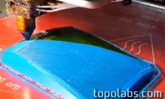
The latest and greatest feature for 3D printers – besides being closed source, having no meaningful technical specs, and being on track towards pulling in $10 Million on a Kickstarter – is automated bed leveling. This amazingly useful feature makes sure your prints have proper adhesion to the bed, reduce print errors, and put even inexpensive printers into the realm of extremely expensive professional machines. Automated bed leveling has been extremely hard to implement in the past, but now [Scottbee] has it figured out with a working prototype on his Makerbot Replicator 2X.

Earlier attempts at automated bed leveling used some sort of probe on the tool head to measure the build plate, calculate its flatness and orientation in space, and compensate for any tilt in software. [Scottbee]’s solution to the problem took a different tack: instead of trying to compensate for any odd orientation of the build surface in software, he’s simply making the bed level with a series of springs and cam locks.

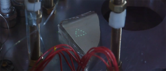
[Scottbee]’s device levitates the build plate on three springs, and replaces the jack screws with three “gimballing pins” and pin locks. With the pin locks disengaged, the bed plate is pressed down with the printer’s nozzle. By moving the extruder across the build plate and locking the pins in place one by one, [Scottbee]’s device defines the plane of the build plate along three points. This makes the build platform parallel to the extruder nozzle, and also has a nice benefit of setting the distance from the build platform to the nozzle precisely with incredible repeatability.

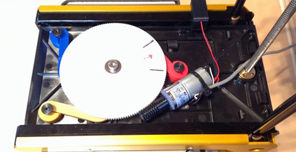
The mechanics of locking the three gimballing pins in place  only requires a single DC gear motor, driven by an extra fan output on the Makerbot’s electronics. It’s simple, and with a bit of rework, it looks like most of the device could also be 3D printed.

An awful lot of RepRaps and 3D printers out there already use three points to attach the build plate to a frame. With a little bit of effort, this same technique could be ported and made a bit more generic than the Makerbot-based build seen above. It’s amazingly simple, and we can’t wait to see this applied to a normal RepRap.

Thanks [Josh] for the tip.

Fixing Apple TV’s Terrible UI

IR

Despite Apple’s unfailing dedication to UI, they still sometimes manage to put out some stinkers. The latest of these is the ‘keyboard’ for the search interface in the Apple TV. It’s an alphabetical keyboard, laid out in a square with the obvious frustration that goes along with that terrible idea. [Lasse] was frustrated with this design and realized searching anything with the Apple TV IR remote is a pain. His solution was to build his own version of the Apple TV remote with a web interface, powered by an Arduino.

Inspired by the Apple Remote Arduino Shield we featured a few years ago, [Lasse] stuck an IR LED int the pins of Arduino with an Ethernet shield, current limiting resistors be damned. The web UI is the innovative part of this build. He’s hosting a simple website on the Arduino that allows him to type – with a real keyboard – a search query into the website, and have the Arduino take care of moving the Apple TV cursor around to select each letter.

The web UI has all the features found on the Apple TV remote, including the swipe gestures, and has a really slick brushed metal texture to boot. You can check out the video of [Lasse]’s project typing text into an Apple TV hilariously fast below.

Continue reading “Fixing Apple TV’s Terrible UI”

Bare-metal Programming On The Teensy 3

Teensy

The Teensy 3.x series of boards are amazing pieces of work, with a tiny, breadboard-friendly footprint, an improbable number of IO pins, and a powerful processor, all for under $20. [Karl Lunt] loves nearly all the features of the Teensy 3, except for one: the Arduino IDE. Yes, the most terrible, most popular IDE in existence. To fix this problem, [Karl] set up a bare-metal development environment, and lucky us, he’s chosen to share it with us.

[Karl] is using CodeBench Lite for the compiler, linker, assembler, and all that other GCC fun, but the CodeSourcery suite doesn’t have an IDE. Visual Studio 2008 Express is [Karl]’s environment of choice, but just about every other IDE out there will do the same job. Of course a make utility will be needed, and grabbing the docs for the Freescale K20 microcontroller wouldn’t be a bad idea, either.

The end result is [Karl] being able to develop for the Teensy 3.X with the IDE of his choice. He was able to quickly set up a ‘blink a LED’ program with the new toolchain, although uploading the files to the Teensy does require the Teensy Loader app.

Electron Beam Control In A Scanning Electron Microscope

Electron

A few years ago [Ben Krasnow] built a scanning electron microscope from a few parts he had sitting around. He’s done a few overviews of how he built his SEM, but now he’s put up a great video on how to control electrons, focus them into a point, and scan a sample.

The basic idea behind a scanning electron microscope is to shoot electrons down a tube, focus them into a point, and scan a conductive sample and detect the secondary electrons shot off the sample and display them on an oscilloscope. [Ben] is generating electrons with a small tungsten filament at the top of his electron ‘stack’. Being like charged, these electrons naturally fan out, so a good bit of electron optics are required to get a small point.

Focusing is done through a series of pinholes and electrostatic deflectors, much like you’d see in an old oscilloscope CRT. In the video, you can see [Ben] shooting electrons and displaying a Christmas tree graphic  onto a piece of phosphor-coated glass. He has a pretty big scanning area in his SEM, more than enough to look at a few chips, wafers, and whatever other crazy stuff is coming out of [Ben]’s lab.

Video below, along with the three-year-old overview of the entire microscope.

Continue reading “Electron Beam Control In A Scanning Electron Microscope”

Hackerspace Tour: IXR In Wall, NJ

IXR2

Update: As of 2023, IXR has been superseded by the Computer Deconstruction Laboratory (CDL). The tools and equipment have obviously seen upgrades in the intervening years since this article was originally published — CDL member Neil Cherry tells us the synths are no longer available, but there is an impressively equipped podcast studio available for rent.


Hackaday took a little trip out to Wall, NJ last weekend for the Vintage Computer Festival 9.1 East. The event was held at Camp Evans, a former US military installation that can only be described as, “The DARPA of a century ago”. This is the site of a Marconi transmitter and the place where [Edwin Armstrong] developed the regenerative receiver a little more than 100 years ago.

There’s a lot more to Camp Evans than the yearly Vintage Computer Festival. It’s also home to the InfoAge Science & History Museums, a collection of fascinating mini-museums covering topics ranging from local shipwrecks to the history of broadcast radio. It’s also the home of IXR, the Institute for eXploratory Research, a hackerspace located in the old telecom building at Camp Evans.

Continue reading “Hackerspace Tour: IXR In Wall, NJ”

Printing In Three Dimensions, For Real This Time

topo

3D printers don’t continuously print in three dimensions – they print one layer, then another, then another. This is true for every single 3D printing technology, but now Topolabs has a very interesting technique that changes that. They’re printing in three dimensions by moving in the Z axis while also printing in the X and Y axes.

The basic idea behind Topolabs’ software is to print a support block, then print an object right on top of the support. The support block can be curved and convex, and the finished product follows the contours of the solid support block. Unlike ‘printing with supports’, the printer extrudes along the X, Y, and Z axes, which should make the finished product much, much stronger.

There are a few drawbacks to the technique – a release agent must be applied to the top of the support block. In the video below, Topolabs is using Kapton, but hair spray or glue sticks will also work. There’s also a limit to how steep an incline a printer can print, determined by the size of the extruder nozzle. Lastly, this technique would be much better suited for a delta-style bot, but the team is getting very good results with a normal Cartesian bot.

You can see a few videos of the Topolabs printing technique below.

Continue reading “Printing In Three Dimensions, For Real This Time”

DIY Linear Actuators For A Flight Sim

[Roland] has already built a few very cool and extremely realistic flight sims, but his latest project will put his current rig to shame. He’s building a six degree of freedom simulator based on homebuilt linear actuators of his own design.

The actuator is powered by a large DC motor moving timing belts along the length of the enclosure. These timing belts are connected to a shaft that’s coupled to the frame with a few bungee cords. The bungee cords are important; without them, the timing belts would be carrying all the load of the sim – not a good thing if these actuators are moving an entire cockpit around a living room.

Also on [Roland]’s list of awesome stuff he’s building for his flight sims is a vibration system based on the BFF Shaker. This board takes data in from sim software and turns it into vibrations produced by either unbalanced DC motors or one of those ‘bass kicker’ transducers.

It’s all very cool stuff, and with all the crazy upgrades [Roland] is doing to his sim rig, he’s doing much better than paying $300/hour to rent a Beechcraft Baron.

Continue reading “DIY Linear Actuators For A Flight Sim”