Adding Shoulder Buttons To An RC Transmitter

radio

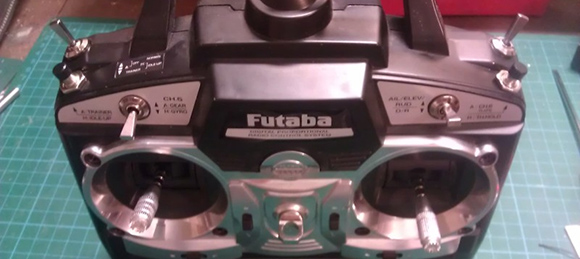
[Gerard] does puppeteering and animatronics work, and to remotely control his creations and characters he uses an off-the-shelf remote control radio. It’s you basic 6-channel setup, but [Gerard] wanted a way to control eye blinks and other simple actions with the press of a button. Sure, he could use the toggle switches on his transmitter, but he wanted something that wouldn’t require turning a servo on and off again. To fix this problem, [Gerard] added shoulder buttons to his transmitter with only a little bit of soldering.

[Gerard]’s transmitter uses toggle switches to send a signal on channels five and six. To add his push buttons, he simply drilled a hole in the plastic enclosure, installed a pair of push buttons, and wired them in parallel to the toggle switches.

Now [Gerard] has momentary switches on channels five and six, perfect for making his creations blink. Since the buttons are wired in parallel with the switches, flicking the switches to the ‘on’ position in effect takes the button out of the circuit, just in case the transmitter gets jostled around.

Gizmo Board, A Tiny X86 Dev Board

Gizmo

With the Raspberry Pi and sever other ARM dev boards seeing their time in the lime light, it’s no surprise other chip manufacturers would want to get in on the action. AMD is releasing a very tiny x86 dev board called the Gizmo, a four-inch square board that shrinks a desktop computer down to the palm of your hand.

The Gizmo is powered by a dual-core x86 Brazos CPU running at 1 GHz with an included Radeon HD 6250 graphics engine. Also on the board is 1GB of DDR3 RAM, a SATA, Ethernet, USB, VGA, Audio, PCI and PCIe ports, and a ton of GPIO pins that include ADCs and DACs. All this in a four-inch square package that boasts about twice the performance of a Raspberry Pi.

While the price of the Gizmo – $200 for an explorer kit – will probably preclude it from being as popular as a Raspberry Pi or other ARM board, sometimes you just need an x86 platform to do the job. With the powerful graphics potential of the Gizmo, we could easily see this board being used in a few computer vision or autonomous robot builds.

New IOIO Is Faster, Cheaper

board-nobg

For the last few years, [Ytai] has been working on the IOIO, a device that connects your Android devices to the other homebrew peripherals. There’s a new version of this really cool board out now that includes a few much-needed features like USB-OTG and a lower component cost that is passed on in savings to you.

A few months ago, our own [Mike Szczys] caught a glimpse of this new IOIO board. It’s the same size as the previous revision, but with USB-OTG, the new IOIO can be a master when connected to a phone, or a slave when connected to a PC.

In addition to USB-OTG, [Ytai] improved the power regulation circuit, and even went so far as to refuse royalties to the board to get the costs down. It’s currently available at Sparkfun for $40.

[Ytai] says he’s working on a few software upgrades to the IOIO, including making capacitive sensing a possibility and including support for stepper motors and controllers. There’s also support for the Raspberry Pi coming up, but we’re just glad [Ytai] managed to put a yo-yo graphic on the bottom silkscreen. Finally, and hopefully, everyone will know how to pronounce IOIO.

Building Your Own Model A Raspberry Pi

A

When the Model A Raspberry Pi is released in the coming weeks or months, you’ll have the opportunity to buy an even cheaper ARM Linux computer that will draw 1/3rd the power of the classic Model B. Some people just can’t wait a month to get their hands on it, so [Blair] decided to make his own.

The Model A Raspberry Pi is nearly the same as the Model B; the only things missing are an Ethernet port, a single USB port, and the associated chips required to drive these ports. In a brave bit of desoldering, [Blair] removed the Ethernet/USB controller with a butane torch.

In part two of [Blair]’s adventures, he removed the Ethernet connector and replaced the two-high USB ports with a single port, greatly decreasing the height of the Raspberry Pi.

As of right now, this is just about the only way to get your hands on the lower power, more compact Raspberry Pi. We can’t wait, though, for the eventual tutorial of how to turn a Model A into a Model B. That’ll be an awesome demonstration of god-like soldering skills.

Raspberry Pi Becomes A Torrent Box

If you’re making a media server out of a Raspberry Pi, why not add an interface to the biggest torrent sites on the Internet? That’s what [Alan] did when he wanted an automated media downloader that can stream movies and TV shows to any device.

[Alan]’s torrent box is basically a web app running on a Raspberry Pi. By accessing the Pi from the browser of a desktop or mobile device, he can search a collection of torrent sites and download just about everything to the Pi with a touch of a button. Once the files are downloaded, the Pi is able to move them to any directory, either locally or on a network, or just serve them up on a TV with a media player.

While we’re not endorsing  file sharing, we can’t think of a simpler way to set up a seedbox that draws a minuscule amount of power. It’s a great addition to any media server, and a great way to get the latest season of <<Linux Distribution>> streaming to your TV.

Fitting A Cold, Metal Heart In An Altoids Tin

sim

[James] has been building a heart rate monitor using a very cool TI chip. He needed a way to test his device, and commercial ECG simulators, like all biotech devices, are absurdly expensive. [James] decided to build his own heart rate simulator, and in the process made a great tool and one of the most well documented projects we’ve ever seen.

Of course, if you’re building an ECG simulator, you’re going to need a good sample of a heart’s electrical pattern. To get this sample, [James] found an old army manual with a diagram of an ideal ECG pattern. [James] took this PDF manual, screen capped the diagram, and used a Python script to generate an array in C the Arduino could repeat over and over.

The rest of the build consisted of a D/A converter, a pot to change the heart rate, a very nice seven-segment display, and a few banana jacks to connect to [James]’ heart monitor. Everything is up in a git, including an amazingly well documented (87 pages!) tutorial for building your own Arduino heart simulator.

Stuffing An NES Into An FPGA

megaman_fpga

When the developer of the µTorrent torrent client and the ScummVM  LucasArts adventure game interpreter gets bored, something cool is bound to happen. Luckily for us, [Ludde] was a bit listless over Christmas, and with more time than energy to burn, implemented a Nintendo Entertainment System on an FPGA dev board.

The NES was powered by a Ricoh 2A03 CPU, a chip nearly identical to the 6502 found in the Commodore 64s and Apple IIs of the early 1980s. There are a few differences between the two, though: the NES CPU includes an Audio Processing Unit on the chip and is connected to a very cool Picture Processing unit elsewhere on the NES. [Ludde] put all these chips in his Spartan-6 FPGA with a lot of Verilog code.

The rest of the system – the RAM, display output, and controller input comes from the peripherals attached to the FPGA dev board. [Ludde]’s specific board didn’t have a good digital to analog converter, so the composite output was traded for a VGA output. It’s not a completely accurate color pallet, but it’s still an amazing piece of work for someone who was simply bored.