The Case Against Calibration Cubes

Calibration cubes have long been a staple for testing and adjusting 3D printers, but according to [Stefan] of CNC Kitchen, they’re not just ineffective—they could be leading us astray. In the video after the break he explains his reasoning for this controversial claim, and provides a viable alternative.

Such cubes are often used to calibrate the steps per millimeter for the printer’s steppers, but the actual dimensions of said cube can be impacted by over or under extrusion, in addition to how far the machine might be out of alignment. This can be further exacerbated by measuring errors due to elephant’s foot, over extruded corners, or just inaccuracies in the caliper. All these potential errors which can go unnoticed in the small 20 x 20 mm cube, while still leading to significant dimensional errors in larger prints

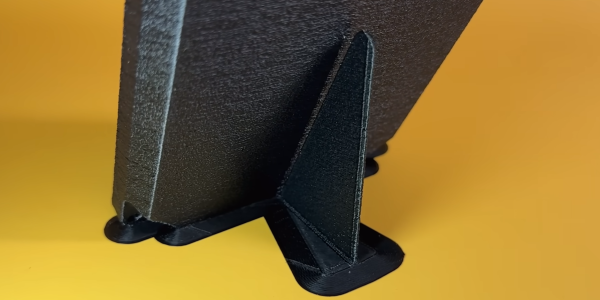
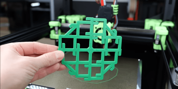
So what’s the solution? Not another cube. It’s something called the “CaliFlower” from [Adam] of Vector 3D. This is not a typical calibration model — it’s carefully designed to minimize measurement errors with ten internal and external measuring points with stops for your calipers. The model costs $5, but for your money you get a complete guide and spreadsheet to calculate the required of corrections needed in your firmware or slicer settings.

If you regularly switch materials in your 3D printer, [Stefan] also advises against adjusting steps per millimeter and suggests defining a scaling factor for each material type instead. With this method validated across different materials like PLA, PETG, ABS, and ASA, it becomes evident that material shrinkage plays a significant role in dimensional inaccuracy, not just machine error. While [Stefan] makes a convincing case against the standard calibration cube for dimensional calibration, he notes that is is still useful for evaluating general print quality and settings.

[Stefan] has always done rigorous testing to back his claims, and this video was no different. He has also tested the effects of filament color on part strength, the practicality of annealing parts in salt, and even printing custom filament.

Continue reading “The Case Against Calibration Cubes”

A Concrete Solution To Balance And Protect Camera Gear

Knocking over expensive camera equipment is an unfortunate occupational hazard when filming projects in a workshop. [Dane Kouttron] wanted to stop sacrificing lights to the cause, so he came up with a practical use for a weeble: A self-stabilizing monopod.

Inspired by a giant scale weeble built by [Colin Furze], [Dane] first did the math to determine the parameters for the build. It’s all about achieving torque equilibrium with a hemisphere of concrete, and [Dane] walks us through the equations, arriving at the conclusion that a 2 lb. camera on 4 foot pole, one needs a hemisphere with a mass of 28 lbs. and a radius of just under 4 inches. To achieve this weight in the given volume would require extra dense concrete with steel shot added.

After some CAD work and 3D printing the 4-part mold was assembled, with RTV silicone sealant acting as both adhesive between the parts and mold release agent. [Dane] first did a test mold with concrete he had laying around. With success achieved, he pursued the real mix but had issues with an error in the concrete-water ratio and the difficulty of mixing in the steel shot. On the second attempt he managed to extract a functional hemisphere from the mold, with the pole held in position during curing by a 3D printed bracket.

The hemisphere bottom of the hemisphere has a flat spot to keep it stable when bumped lightly. [Dane] added a Manfroto quick-release mount to the end of the pole to allow easy attachment of lights and cameras. It might be a bit hefty to carry around, but it’s takes up less floor space than a tripod and is sure to save [Dane] from expensive bumps-turned-crashes.

Camera cranes, small and large, are another great tool for workshop cinematography. For sheer overkill it would be hard to beat an 8-axis workshop-sized motion control robot.

High Caliber Engineering On A Low Torque PCB Servo Motor

Building a 3D motor printed motor is one thing, but creating a completely custom servo motor with encoder requires some significant engineering. In the video after the break [365 Robots] takes us through the build process of a closed-loop motor with a custom optical encoder.

The motor, an axial flux design, uses a stack of 0.2mm PCBs with wedge shaped coils clamped in a 3D printed body. It’s similar to some of the other PCB motors we’ve featured, but what really sets this build apart is its custom optical encoder, which was a project in its own right. The 4-bit absolute position encoder uses IR LEDs to shine through an PCB disc with concentric gray code copper encoder rings onto IR receivers. This works because FR4, the composite material used in PCBs doesn’t block IR light.

The motor’s body was printed from ABS to withstand the heat during operation. [365 Robots] didn’t skimp on the testing either, creating a 3D printed closed-loop test stand with load cell and Arduino. Like other PCB motors it produces very little torque, roughly 2% of a typical NEMA17 stepper motor. Even so, the engineering behind this project remains impressive.

Continue reading “High Caliber Engineering On A Low Torque PCB Servo Motor”

3D Mouse With 3D Printed Flexures And PCB Coils

3D mice with six degrees of freedom (6DOF) motion are highly valued by professional CAD users. However, the entry-level versions typically cost upwards of $150 and are produced by a single manufacturer. [Colton Baldridge] has created the OS3M Mouse — an open source alternative using PCB coils and 3D printed flexures.

The primary challenges in creating a 6DOF input device, similar to the 3Dconnexion Space Mouse, lie in developing a mechanical coupling that enables full range motion, and electronics capable of precisely and consistently measuring this motion. After several iterations of printed flexure combinations and trip down the finite element analysis (FEA) rabbit hole, [Colton] had a working single-piece mechanical solution.

To measure the knob’s movement accurately, [Colton] employs inductive sensing. Inductance to Digital Converters (LDCs) assess the inductive alterations across three pairs of PCB coils, each having an opposing metal disk mounted on the knob. This setup allows [Colton] to use a Stewart platform‘s kinematic model calculate the  knob’s relative position. The calculation are done on an STM32 which also acts USB HID send the position data to a computer. For the demo [Colton] created a simple C++ app to translate the position data to Solidworks API calls.

Continue reading “3D Mouse With 3D Printed Flexures And PCB Coils”

A Paddle Wheel Ground Effect Vehicle

Who said paddle wheels were just for leisurely riverboat cruises? [rctestflight] is smashing that image with a high-speed twist on the concept, using paddle wheels to propel a ground effect vehicle across water. In the video after the break, witness this blend of old and new as he tests various designs.

Over the past few years he’s worked on a series of ground effect vehicles which exploits the increased lift and reduced drag when flying close to a surface. Unlike full-sized counterparts, smaller RC models struggle to stay in this sweet spot due to less pronounced self-stabilizing feedback loops. This means a small scale vehicle tends to touch the water rather often, and bleeding a lot of momentum in the process.

He wanted to convert these losses into gains by giving the vehicles a boost of speed whenever it touches the water. It’s a popular trick with RC cars which will hydroplane for long distances as long as they can maintain speed. All the designs still required air propellers for takeoff and to help maintain speed. The final design didn’t really need the paddle wheel when the air and water was calm, but it definitely helped when things got choppy. He is already experimenting with different paddle designs but also plans to test some other types of surface drives.

For covered a number off small scale ekranoplans, including a previous version by [rctestflight] that uses lidar for altitude control. He has also collaborated with [Think Flight] to build a autonomous small scale prototype for a maritime shipping startup.

Continue reading “A Paddle Wheel Ground Effect Vehicle”

Massive Water Rocket Is Impressive But Accessible

Water rockets are one of those projects that never get old, and bumping the size just adds to the challenge. In the video after the break, [ARRO Rockets] takes us through the launch of Gamma IV, his most ambitious water rocket project yet. Crafted with spliced soda bottles and standard household materials, this rocket is a testament to what one can achieve with simple components and a bit of ingenuity.

The rocket’s release mechanism demonstrates this — employing nothing more than a quick connect hose connection and a basic pulley system. The parachute recovery system is also a nice combo of modern electronics and simplicity. It uses a microcontroller with accelerometer to detect the apogee, and release the parachute to be ejected by another piece of soda bottle acting as a spring. It also records or the flight data on an SD card.

[ARRO Rockets] had some trouble with friction on the launch rail, which was partially solved with liberal application of silicone spray. The root cause might be the rail button flexing on launch, or just the change of the pressurized bottles.

We are especially impressed by how accessible this project is, a reminder that high-flying achievements don’t necessarily require deep pockets or hard-to-source parts. The entire setup is not only cost-effective but also opens up numerous possibilities for further experimentation and refinement, like adding a second stage or a precision release mechanism.

Continue reading “Massive Water Rocket Is Impressive But Accessible”

Cockpit of a Hawker Siddeley Trident with the moving map display

A Live Map Display In A 1960s Airliner

We tend take GPS navigation for granted these days, so it’s easy to forget that it became only available in the last few decades. Aviation navigation used to be significantly more challenging, so how was the Hawker Siddeley Trident, a 1960s airliner, fitted with a live updating map display? In a fascinating dive into aviation history the British Airliner Collection has spun up an insightful article on the magic behind these moving map displays.

Without access to satellite navigation or advanced electronics, engineers had to get creative. Enter the Trident’s moving map display, a marvel of ingenuity that predated the GPS systems. Using a combination of Doppler radar and some clever mechanics, pilots could accurately determine their position without relying on any external signals.

The system makes use of four Doppler radar beams, arranged in what was known as the Janus array. This configuration corrected for errors caused by changes in altitude or wind drift, ensuring accurate ground speed readings. The movable antennas mounted under the cabin floor could adjust its orientation to maintain alignment with the actual direction of travel, calculating drift angle precisely. Combined with compass information and flight time from a known start point to to indicate the current position with a pointer on a rolled paper map. The system was well ahead of it’s time, and significantly easier to use and more accurate than the Decca radio navigation system in use at the time.

It’s mind boggling to see the solutions engineers came up with without much of the digital technology we take for granted today. Gyroscopes for inertial navigation, the cavity magnetron for radar and radial engines were all building blocks for modern aviation.

Thanks for the tip [poiuyt]!