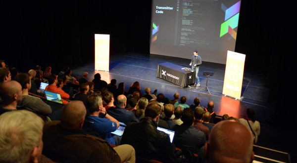
Review: LimeSDR Mini Software Defined Radio Transceiver

It’s fair to say that software-defined radio represents the most significant advance in affordable radio equipment that we have seen over the last decade or so. Moving signal processing from purpose-built analogue hardware into the realm of software has opened up so many exciting possibilities in terms of what can be done both with more traditional modes of radio communication and with newer ones made possible only by the new technology.

It’s also fair to say that radio enthusiasts seeking a high-performance SDR would also have to be prepared with a hefty bank balance, as some of the components required to deliver software defined radios have been rather expensive. Thus the budget end of the market has been the preserve of radios using the limited baseband bandwidth of an existing analogue interface such as a computer sound card, or of happy accidents in driver hacking such as the discovery that the cheap and now-ubiquitous RTL2832 chipset digital TV receivers could function as an SDR receiver. Transmitting has been, and still is, more expensive.

The LimeSDR Mini's chunky USB stick form factor.
The LimeSDR Mini’s chunky USB stick form factor.

A new generation of budget SDRs, as typified by today’s subject the LimeSDR Mini, have brought down the price of transmitting. This is the latest addition to the LimeSDR range of products, an SDR transceiver and FPGA development board in a USB stick format that uses the same Lime Microsystems LMS7002M at its heart as the existing LimeSDR USB, but with a lower specification. Chief among the changes are that there is only one receive and one transmit channel to the USB’s two each, the bandwidth of 30.72 MHz is halved, and the lower-end frequency range jumps from 100 kHz to 10 MHz. The most interesting lower figure associated with the Mini though is its price, with the early birds snapping it up for $99 — half that of its predecessor. (It’s now available on Kickstarter for $139.)

Continue reading “Review: LimeSDR Mini Software Defined Radio Transceiver”

Unbricking A 3D Printer The Hard Way: By Writing A Bootloader

There’s a sinking feeling when a firmware upgrade to a piece of equipment goes wrong. We’ve all likely had this happen and  bricked a device or two. If we are lucky we can simply reapply the upgrade or revert to a previous version, and if we’re unlucky we have to dive into a serial debug port to save the device from the junk pile. But what happens when both those routes fail? If you are [Arko], you reverse-engineer the device and write your own bootloader for it.

The offending bricked object was a Monoprice MP Mini Delta 3D printer to which he was foolhardy enough to apply new firmware after seeing a friend’s machine taking it without issue. Finding the relevant debug interface on its main PCB he applied the firmware upgrade again, only to realise that in doing so he had overwritten its bootloader. The machine seemed doomed, but he wasn’t ready to give up.

What follows in his write-up is a detailed examination of the boot mechanism and memory map of an ARM Cortex M0 processor as found in the Monoprice’s STM32F070CB. We learn about vector tables for mapping important addresses of interrupts and execution points, and the mechanics of a bootloader in setting up the application it launches. This section is well worth a read on its own, even for those with no interest in bricked 3D printers.

In the end he had a working bootloader to which he appended the application firmware, but sadly when he powered up the printer there was still no joy. The problem was traced to the serial connection between the ARM doing the printer’s business and the ESP8266 running its display. After a brainstorm suggestion with a friend, a piece of code was found which would set the relevant registers to allow it to run at the correct speed.

So after a lot of work that resulted in this fascinating write-up, there was a working 3D printer. He suggests that mere mortals try asking Monoprice for a replacement model if it happens to their printers, but we’re extremely glad he persevered. Without it we would never have had this fascinating write-up, and would be the poorer without the learning experience.

This isn’t the first time we’ve brought you 3D printer bootloader trickery.

FPGA Magic Puts Little Embedded Screens Up On The Big Screen

Old-school handheld gaming platforms have a certain charm, but it’s fair to say that their relatively tiny screens don’t lend themselves to wider viewing. This presented a problem to [uXe] who wanted to display Arduboy games on the big screen, so he took a MyStorm BlackIce FPGA board and created a converter that emulates a SSD1306 OLED display and has a VGA output.

Having proved the viability of the idea, it was ported to a dedicated PCB with onboard ancillaries such as a level shifter for a 5 volt input. In an exciting twist, with a few modifications it’s also emulated a GameBoy screen, allowing full-sized playable games from that platform too. But the power of this hack isn’t relegated to gaming. SSD1306 is just one of a few different common standards for embedded displays. The FPGA work in this project is the blueprint for building a VGA adapter for any number of display replacements. We’d love to see an HD44780 mod of this!

The result as you can see in the video below the break is very much more in the spirit of the OLED than an HD immersive experience. But it does have a very pleasing air of an older arcade machine about it.

Several projects starting on a MyStorm BlackIce board have made it here in the past. Pretty memorable is the BBC Micro clone using one.

Continue reading “FPGA Magic Puts Little Embedded Screens Up On The Big Screen”

Android Sources For The Asus Tinker Board

The Asus Tinker Board is one of the quiet achievers of the powerful single board computer market. A Raspberry Pi form factor with a significantly more powerful processor, more memory, faster networking, and Asus build quality. In hardware terms it leaves many of the other Pi competitors in the dust. If the Tinker Board has a problem though it is the same one that affects so many otherwise promising offerings, that its software support isn’t as strong as the fruity computer from Cambridge. When you buy a Pi it’s Raspbian that makes it a wise purchase, along with the huge community support that surrounds it.

An interesting development on that front comes courtesy of [Justin], who tells us that the sources have been released for the Tinkerboard flavour of Android. The community have put in the work on the board’s Linux distro, but the Android side hasn’t had the same opportunity. This step makes the Tinker Board a significantly more interesting choice for custom Android development, as unlike some of its competitors for which only precompiled builds are available it puts a bespoke Android build in the hands of its developers.

We like the Tinker Board here at Hackaday. We first reviewed it when the boards became available, but later found that they had reached the market in error before Asus had a stable operating system. We therefore returned with another review six months later, and found it to be a credible Raspberry Pi alternative saved by its band of enthusiasts who have filled in for any of its software shortcomings.

Only Mechanical Relays Will Do For Automated Hi-Fi Audio Source Switching

If you are a devotee of audiophile-quality analogue hi-fi, switching between sources simply can not be done through a solid-state device. Only physical switches will do because they come without the risk of extra noise or distortion that their silicon equivalents might bring.

That is the philosophy that lies behind [Skrodahl]’s relay-based audio switching board, which boasts 5 high-quality relays each handling a stereo input, with their control passed either to a rotary switch or to an ESP32 module. The ground connections on audio and switching sides are isolated from each other to avoid transient noise finding its way to the speakers.

You might think that an audio switching board is a very simple device indeed and thus not worthy of Hackaday’s attention, but it’s surprisingly easy to make a mess of a module like this one and they have put in some effort to avoid the pitfalls. The metal-can version of the switching transistors seems a little overkill, but fancy audio is a funny business.

If the ESP isn’t your bag, we’ve brought you another relay based audio switcher in the past that used an Atmel chip.

An Autonomous Drone For Working Rare Squares

Amateur radio is an extremely broad church when it comes to the numerous different activities that it covers. Most of the stories featuring radio amateurs that we cover here have involved home-made radios, but that represents a surprisingly small subset of licence holders.

One activity that captivates many operators is grid square collecting. The map is divided into grid squares, can you make contact with all of them? Land-based squares in Europe and North America are easy, those in some more sparsely populated regions a little less so, and some squares out in the ocean are nigh-on impossible. As an attempt to solve this problem, the Jupiter Research Foundation Amateur Radio Club have put an HF transceiver and associated electronics in a WaveGlider autonomous seagoing vehicle. The idea is that it will traverse the ocean, and you can work it, thus getting the contact you require to add those rarest of grid squares to your list.

The transceiver in question is a commercial portable one, an Elecraft KX3, and the brain of the payload is a Raspberry PI. It’s operating the FT8 mode, and will respond to a call on 14074 kHz in an automated fashion (Or it would, were its status page not telling us that it is offline due to power issues). It’s currently somewhere in the Pacific ocean, having been at sea now for a couple of months.

We spotted this through a spirited online discussion as to whether working an automated station is really a proper contact at all, with one amateur commenting that it might be a way for him to keep on going post mortem. But the ethics of the contact aside, it’s an extremely interesting project and one we hope eventually will come back online.

Thanks Sotabeams, via [AE5X].

A Simple POV Business Card

The business card is an odd survivor from the past, when you think about it. When a salesman in a Mad Men style suit stepped out of his Studebaker and walked past a room full of typists to the boss’s wood-paneled office, he would have handed over a card as a matter of course. It would get filed away in the Rolodex.

These days, making your card stand out from the crowd of print-shop specials has become an art form. In our community this extends to cards with integrated electronics, such as this one with a persistence-of-vision display driven by an ATtiny from [James Cochrane], shown in the video below.  It’s by no means the first such card, but he takes us through its design and construction in great detail which makes the video below the break worth a look. If you have never made a toner transfer PCB for example, you can see how his was made.

He makes the point that while a POV spinner needs only to display in one direction, a card has to be waved back and forth. Thus it needs to change the direction of its display, and needs a tilt sensor to activate this. His construction method uses through-hole components, but is surface mount in that they are soldered to the top surface of the board. The result is a rather attractive POV card that maybe isn’t something you’d hand out to all and sundry, but perhaps that’s not the point.

Continue reading “A Simple POV Business Card”