You’ve Never See A Solid-State Oscilloscope Like This One

Remember a the time before oscilloscopes had a brain? It’s easy to forget as we’ve become accustomed to a class of simple solid state oscilloscope using a microcontroller as signal processor and a small LCD display to show the resulting waveforms. They are commonly available as inexpensive kits, and while their bandwidth is not huge they give a good account of themselves in low frequency applications. But of course, originally the signal processing was handled in a much simpler way.

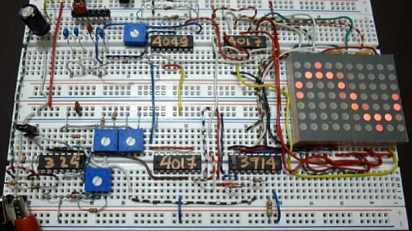
[SimpleTronic] reminds us that a small solid state oscilloscope does not need a microcontroller, with a ‘scope on a breadboard that displays waveforms on an LED matrix in a much more traditional manner. This is very much an analogue oscilloscope, in which the X deflection circuitry of the CRT is replaced by a decade counter stepping through the columns of LEDs on the display, and the Y deflection circuitry by some analogue signal conditioning followed by an LM3914 bar graph display chip driving the display rows. There are a few refinements such as a trigger circuit, but it remains a very understandable and surprisingly simple device.

It has a claimed bandwidth of 40 kHz defined by its sweep ranges rather than its analogue bandwidth, and an input voltage range from 50 mVpp to 50 Vpp. It’s hardly a useful instrument due to its low bandwidth, but its strength lies in novelty and in understanding a traditional oscilloscope rather than in its utility. You can see it in action in the video we’ve placed below the break.

‘Scopes of limited use appear from time to time on these pages. A favourite of ours is this soldering iron.

Continue reading “You’ve Never See A Solid-State Oscilloscope Like This One”

The Electric Vehicles Of Electromagnetic FIeld: The Selby

A couple of weekends ago on a farm in rural England with a cider orchard and a very good line in free-range pork sausages, there was the first get-together of the nascent British Hacky Racers series of competitions for comedic small electric vehicles. At the event, [Mark Mellors] shot a set of video interviews with each of the attendees asking them to describe their vehicles in detail, and we’d like to present the first of them here.

The Selby is unique among all the Hacky Racers in being a six-wheeler. It’s the creation of [Michael West] of MK Makerspace, and it bears a curious resemblance to a pair of PowaKaddy golf buggies grafted together. The resulting vehicle has four driven wheels and two steering wheels, and though it is hardly a speedy machine this extra drive gives it what is probably the most hefty pulling power of all the contestants. In the video below it appears without bodywork, but we are told that something impressive will sit upon it when it appears at Electromagnetic Field.

View of motors fed with 24 V driving the rear wheels

I should own up, that the Selby is a familiar to Hackaday, as I’m also an MK Makerspace member. I’ve seen it progress from two worn-out golf trolleys to its current state, and seen first hand some of the engineering challenges that has presented. The PowaKaddy buggies of that vintage are extremely well-engineered, with a Curtis controller that is still comfortably within spec even when driving four motors instead of two. Unusually for a Hacky Racer the power comes from a pair of huge lead-acid batteries, as these were the power source supplied with the PowaKaddy from new and it made little sense to change them. Gearing is fixed at golf-course speeds, and braking comes from a pair of brakes fitted on the motors. The motors themselves are simple DC affairs, with significant weatherproofing.

Cutting and shutting the two PowaKaddys was straightforward enough, but introduced a warp to the chassis that was solved by your Hackaday scribe hanging on the end of a lever formed from a long piece of 4-by-2 while [Mike] and friends stood on the other end of the Selby.

As a driving experience it’s exciting enough but lacks the speed of some of its competitors. Where it really comes into its own though is off-road, as the multi-wheel drive and broad treaded tyres power it across mud and offer powersliding opportunities on wet grass.

We’ve covered a couple of Hacky Racers so far in our mini-series on the Electric Vehicles of Electromagnetic Field, and we’ll bring you a few more before the event. Meanwhile feast your eyes on a Sinclair C5, and an Austin 7 inspired mobility scooter conversion.

Continue reading “The Electric Vehicles Of Electromagnetic FIeld: The Selby”

Guardin, Guarding The Garden: Turn Raspberry Pi Into A 3rd Eye

If you are a gardener, you’ll know only too well the distress of seeing your hard work turned into a free lunch for passing herbivorous wildlife. It’s something that has evidently vexed [Jim], because he’s come up with an automated Raspberry Pi-controlled turret to seek out invading deer, and in his words: “Persuade them to munch elsewhere”.

Before you groan and sigh that here’s yet another pan and tilt camera, let us reassure you that this one is a little bit special. For a start, it rotates upon a set of slip rings rather than an untidy mess of twisted cables, so it can perfom 360 degree rotations at will, then it has a rather well-designed tilting cage for its payload. The write-up is rather functional but worth persevering with, and he’s posted a YouTube video that we’ve placed below the break.

This is a project that still has some way to go, for example just how those pesky deer are to be sent packing isn’t made entirely clear, but we think it already shows enough potential to be worthy of a second look. The slip ring mechanism in particular could find a home in many other projects.

It’s worth reminding readers that while pan and tilt mechanisms can be as impressive as this one, sometimes they are a little more basic.

Continue reading “Guardin, Guarding The Garden: Turn Raspberry Pi Into A 3rd Eye”

Measure Resistance The Colourful Way

One of the first things anyone with an interest in electronics learns is the resistor colour code. The colour of the first band reveals the first figure, the second the subsequent figure, and the third a power-of-ten multiplier. At first you learn these colours, but eventually you just recognise the values through familiarity. You don’t have to think about multipliers when you see orange-orange-red, you just know that it’s a 3K3 resistor.

[Plusea] has come up with an entertaining interface for an ohmmeter, which instead of displaying the resistance on an LCD or a meter shows it as the colours of the code, via a set of addressable LEDs. The work is done by an ATtiny85 microcontroller, and the whole thing is mounted on a flexible PCB (fabrication of which is itself interesting, placing cut copper traces on a sheet of kapton and covering with a second kapton layer cut to be the solder mask). There is even a clever integration of a CR2032 battery holder from the PCB itself, though they admit that it could be made more compact with the use of SMD components instead of through-hole.

The write-up and associated photo album tells us a lot about the project, but is missing a crucial detail: a shot of it working. We’ll give them the benefit of the doubt on that front though, because we like the idea and its execution.

Strangely, this isn’t the first ohmmeter to use the resistor colour code in this way, we’ve previously brought you one featuring a light-up giant resistor.

The Forgotten Art Of Riveted Structures

If you are in the habit of seeking out abandoned railways, you may have stood in the shadow of more than one Victorian iron bridge. Massive in construction, these structures have proved to be extremely robust, with many of them still in excellent condition even after years of neglect.

A handsome riveted railway bridge, over the River Avon near Stratford-upon-Avon, UK.

When you examine them closely, an immediate difference emerges between them and any modern counterparts, unlike almost all similar metalwork created today they contain no welded joints. Arc welders like reliable electrical supplies were many decades away when they were constructed, so instead they are held together with hundreds of massive rivets. They would have been prefabricated in sections and transported to the site, where they would have been assembled by a riveting gang with a portable forge.


So for an audience in 2018, what is a rivet? If you’ve immediately thought of a pop rivet then it shares the function of joining two sheets of material by pulling them tightly together, but differs completely in its construction. These rivets start life as pieces of steel bar formed into pins with one end formed into a mushroom-style dome, probably in a hot drop-forging process.

A rivet is heated to red-hot, then placed through pre-aligned holes in the sheets to be joined, and its straight end is hammered to a mushroom shape to match the domed end. The rivet then cools down and contracts, putting it under tension and drawing the two sheets together very tightly. Tightly enough in fact that it can form a seal against water or high-pressure steam, as shown by iron rivets being used in the construction of ships, or high-pressure boilers. How is this possible? Let’s take a look!

Continue reading “The Forgotten Art Of Riveted Structures”

The Engineering Of An Ultrasonic Phased Array

Ultrasonic phased arrays are one of the wonders of the moment, with videos of small items being levitated by them shared far and wide. We’ve all seen them and some of us have even wondered about building them, but what about the practical considerations? Just how would you drive a large array of ultrasonic transducers, and how would you maintain a consistent phase relationship between their outputs? It’s a problem [Niklas Fauth] has been grappling with over the three iterations so far of his ultrasonic phased array project, and you can follow his progress on the latest build.

The arrays themselves are a 16 by 16 grid of cheap ultrasonic transducers on a PCB, fed by HV583 high-voltage shift registers. These chips have proven to be particularly problematic, their drivers having a relatively high internal resistance which leaves them prone to overheating.

An interesting solution to a problem comes from the transducers having a polarity, but because it doesn’t matter in their usual application, that polarity not being marked. He’s overcome this by using the STM32 he has managing power alongside his BeagleBone to listen through a sensor as the ‘Bone supplies each transducer in turn with a known phase. An internal map can then be created, such that the appropriate phase can be applied on a transducer-by-transducer basis.

It’s the fascination with the subject that we find appealing, this is version three and version two worked. Most of us would make one and call it a day. It’s something we’ve seen before from [Niklas], after all this is someone who plays with turbomolecular pumps for fun. Meanwhile if you would like to learn more about ultrasonic arrays and acoustic levitation, it was the subject of one of this year’s Hackaday Belgrade talks.

An Achievable Underwater Camera

We are surrounded by sensors for all forms of environmental measurement, and a casual browse through an electronics catalogue can see an experimenter tooled up with the whole array for a relatively small outlay. When the environment in question is not the still air of your bench but the turbulence, sand, grit, and mud of a sea floor, that pile of sensors becomes rather useless. [Ellie T] has been addressing this problem as part of the study of hypoxia in marine life, and part of her solution is to create an underwater camera by encasing a Raspberry Pi Zero W and camera in a sturdy enclosure made from PVC pipe. She’s called the project LoBSTAS, which stands for Low-cost Benthic Sensing Trap-Attached System.

The housing is simple enough, the PVC has a transparent acrylic disk mounted in a pipe coupler at one end, with the seal being provided at the other by an expansion plug. A neopixel ring is mounted in the clear end, with the Pi camera mounted in its centre. Meanwhile the Pi itself occupies the body of the unit, with power coming from a USB battery bank. The camera isn’t the only sensor on this build though, and Atlas Scientific oxygen sensor  completes the package and is mounted in a hole drilled in the expansion plug and sealed with silicone sealant.

Underwater cameras seem to have featured more in the earlier years of Hackaday’s existence, but that’s not to say matters underwater haven’t been on the agenda. The 2017 Hackaday Prize was carried off by the Open Source Underwater Glider.