You might expect that sourcing live algae would be as simple as scraping up a bit of green slime from a nearby pond, but that yields an uncertain mix of species. [Severin] wanted Chlorella algae for his experiment because its high fat content makes it suitable for biodiesel experiments, so had to source his culture from an aquatic shop.
The reactor takes the form of a spiral of transparent plastic tube surrounding a CFL lamp as a light source, all mounted on a lasercut wooden enclosure housing a pump. A separate glass jar forms a reservoir for the algal-rich water. He does not mention whether or not he adds any nutrient to the mix.
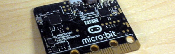
The little board that has at times seemed so plagued with delays as to become the Duke Nukem Forever of small computers has finally shipped. A million or so British seventh-grade schoolchildren and their teachers will today start receiving their free BBC micro:bits.
Announced early last year, the plan was to rekindle the learning of code in schools through handing out a powerful and easy to program small computer to the students. The hope is that it will recapture the spirit of the 1980s, when school computing meant programming Acorn’s BBC Micro rather than learning how to use Microsoft Word.
Sadly the project has been delayed multiple times, the original target of last October was missed, and a revised estimate from January suggested they might ship at half-term (about four weeks ago). With only a few days to go before the Easter school holidays the kids will have to try them out at home, but at least they’re arriving. Continue reading “British Kids Finally Get Their Micro:Bits”→
As a fresh-faced electronic engineering student while the first Gulf War was raging in a far-off desert, I learned my way through the different families of 74 logic at a university in the North of England. 74LS was the one to use, the story went, because it’s quick and doesn’t use much power. At the time, there was an upstart on the scene: 74HC. Now that’s really quick. New. Exotic, even.
Thus an association was formed, when you want a quick logic function then 74HC is the modern one to go for. It could have been a lifelong love affair, but over twenty years, after many factors of speed increases and some RF tricks with gates we wouldn’t have dreamed of back then, it’s over. There is a whole world of newer logic families to choose from, and while HC is still good at what it does, it’s well past time to admit that it may just have been superseded.
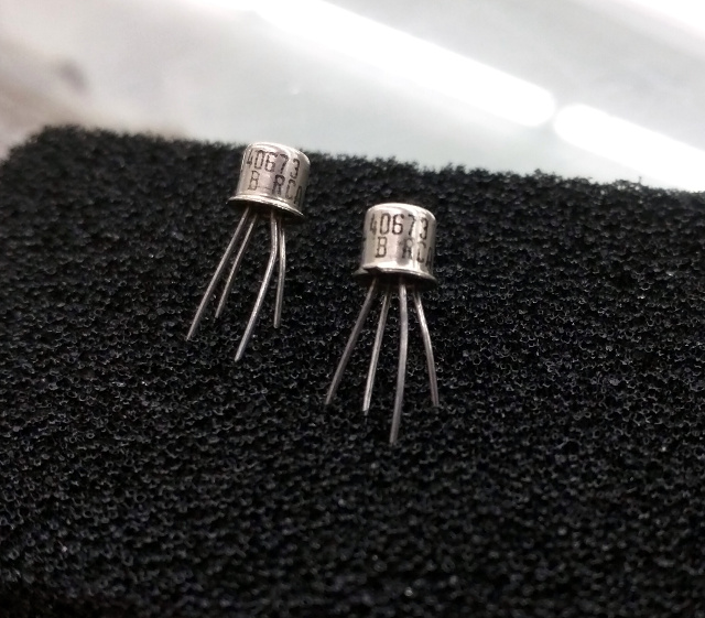
40673s, probably now worth more by weight than anything else on four legs. (Thanks are due to [Brandon Dunson] and Tanner Electronics) A tendency to cling to the past with logic families is pretty harmless. Like [Adam Fabio]’s TIP power transistors they’re pretty cheap, still very much in production, and still do most jobs demanded of them excellently. But what prompted this piece was a far more egregious example of an old component still being specified: the RCA 40673 dual-gate MOSFET. Launched in the mists of time when dinosaurs probably still roamed the earth, this static-sensitive four-pin TO72 found a home in a huge variety of RF amplifiers, oscillators, and mixers. It worked well, but as you might expect better devices came along, and the 40673 was withdrawn some time in the 1980s.
Unfortunately, nobody seems to have told a section of the amateur radio community about the 40673’s demise. Or perhaps nobody’s told them that many scrap analogue TV tuners of a certain age will yield a perfectly good newer replacement for free. Because even today, thirty years after the 40673 shuffled off this mortal coil, you can still find people specifying it. If you have a stash of them in your junk box, they’re worth a small fortune, and yours could be the bench with the throng of people at the next ham radio convention.
A different but equally annoying manifestation of the phenomenon comes when the device everyone likes to specify is not very old and very much still in production, but the designer hasn’t taken the time required to check for a cheaper alternative. Nobody ever got fired for buying IBM, they say, but perhaps they should be fired for specifying an AD8307 logarithmic amplifier in an amateur radio power meter. Don’t take this the wrong way, it’s a beautiful chip and probably a lot of work at Analog Devices has gone into laser-trimming resistors to make it perform to an extremely demanding specification. But eleven dollars for a chip? When a cursory search will turn up Maxim’s MAX9933 which does a perfectly good job in this application at well under two dollars? Someone isn’t doing their homework.
Sometimes there are components for which there are no perfect replacements. Germanium point-contact diodes, for example. 1N34As and OA91s are becoming like hen’s teeth these days, and though Schottky diodes can replace them in many applications, there are still a few places if you’re a radio person you’ll hanker for the original. There are suppliers on Alibaba who claim to manufacture 1N34s, but the pictures always look suspiciously like 1N4148s, and anyway who can find a home for a hundred thousand diodes? (Hang on, this is Hackaday. There will be someone out there with a hundred-thousand-diode project, you can count on it.)
OK, maybe germanium diodes are an edge case and the examples above have a radio flavour, but you get the picture. What the full-blown rant in the previous paragraphs has been building up to is this: a plea for designers to do their homework. Please try to design every project for the next two decades, and as though any extras in the component price come from your company’s bottom line. (We’ll make exceptions for building something for which the whole point is a retro circuit. An Apple I replica like the Mimeo 1 needs old logic chips for artistic purposes.)
Is there a vital electronic engineering skill that’s being lost here perhaps? Back when the Internet was the sole preserve of boffins and Tim Berners-Lee hadn’t yet plugged his hypertext ideas into it, we relied on catalogs. Big paper-bound books the size of telephone directories were our only window into the exciting world of electronic components. If you’re an American yours was probably from Radio Shack, but for most UK-based hackers and makers who couldn’t get their hands on a commercial account from RS or Farnell that meant the Maplin catalogue. Before they moved in a consumer-electronics direction, they were a component specialist whose catalogue with its distinctive spaceships on the cover could be bought at large newsstands.
It’s difficult to describe the impact of electronics catalogues in the ’70s and ’80s to someone who has known only the abundance of information from the WWW. These publications were our only window into the world of electronic components. They contained significant excerpts from semiconductor data sheets, and we read their wealth of information from cover to cover. We knew by heart what each device was capable of, and we eagerly devoured each new tidbit of information as it arrived.
In short, when we specified a component, we did so with a pretty good knowledge of all the components that were available to us.
By comparison, nowadays we can quickly buy almost any device or component in production from a multitude of suppliers. There are millions more devices available, and if RS or Farnell don’t have the part then Mouser or Digi-Key are sure to provide. The WWW allows us to find what we need in short order, and the miracle of global distribution means that we can have it delivered within 48 hours almost wherever we live.
CPC’s very aptly-named Big Book
Which means that all the new devices are available to us, but we’ve lost the ability to keep on top of them. We’ve become information rich, but knowledge poor. Printed catalogs still exist, but the sheer volume of information they contain forces brevity upon their entries and expands the size of the publication to the point at which it becomes an unwieldy work of reference. We therefore tend to stick with the devices and components we know, regardless of their cost or of whether they have been superseded, and our work is poorer for it.
We need to relearn the skill of inquisitiveness when it comes to the parts we use, and to rediscover the joy of just browsing, even if the medium is now a huge suppliers’ web site rather than a paper catalog. Otherwise we’ll still be looking at circuit diagrams containing 74LS logic and 40673 MOSFETs in the 2030s, and that can’t be a good thing!
There is of course also a slightly macabre alternative scenario. The highest online price we found for 40673s was over $30 each, so if a producer can make that kind of silly money then there’s a danger that RCA’s successors will see a business model in exhuming the corpse and re-animating it, thus ensuring that we’ll never be free of the undead. We need to make sure that doesn’t happen!
It’s safe to say that the Internet of Things is high on the list of buzzwords du jour. It was last seen rapidly ascending towards the Peak of Inflated Expectations on the Gartner Hype Cycle, and it seems that every startup you encounter these days is trying to place an IoT spin on their offering. Behind all the hype though lie some interesting wireless technologies for cheaply making very small microprocessors talk to each other and to the wider world.
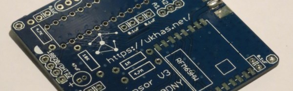
Today we’d like to draw your attention to another wireless technology that might be of interest to Hackaday readers working in this area. UKHASnet is a wireless network developed from within the UK high-altitude ballooning community that uses cheap licence-exempt 868MHz radio modules in Europe and 915MHz in the Americas. The modules they are using have a surprisingly usable power output for licence exempt kit at 100mW, so the system has been designed for extensibility and bridging through nodes mounted on balloons, multirotors, or even seaborne buoys.
All UKHASnet packets are sent as human-readable plaintext ASCII, and the system borrows some of the features of amateur radio’s APRS. All packets are considered unreliable, all nodes repeat the packets they receive with their own node ID appended, and there are gateway nodes that make the packets available to the internet. There is a repeat number built into each packet to stop packets continuing ad infinitum.
This network differs from its commercial counterparts in that it has no proprietary IP or licencing from a standards body. And despite the name, you don’t have to be in the UK to use it. All data is in the clear, and thus it is likely that you won’t see it in mass-market commercial products. But it is exactly these features that are likely to make it attractive to the maker community. Your scribe will probably not be the only person who goes away from this article to suggest that their local hackspace finds the space for a UKHASnet node.
This is the first time we’ve featured UKHASnet here at Hackaday. Plenty of projects using licence-free radio modules have made it onto these pages, though, including this extreme-range remote controller for model aircraft, and this weather station sensor network that could have probably found UKHASnet useful had its creator had it to hand.
What do you do, when you want an ohm? What is an ohm, for that matter? Take a wander over to the textbook definitions, and you’re soon deep in a world of coulombs and parallel infinite planes one meter apart in a vacuum that you probably only half remember from your high school physics class. It’s hard work, this metrology lark.
Of course, you can just order a resistor. A few cents each when you’re buying small quantities or much less when you’re buying a reel of five thousand, and there you have it. An ohm. Only it’s not really an ohm, more like nearly an ohm. Within 1% of an ohm is pretty good, but Vishay or Bourns or whoever don’t have the margins to get philosophical about those infinite planes when you’re only giving them a few cents.
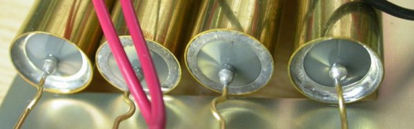
When you REALLY want an ohm, you buy a standard resistor, and you pay a more significant sum. You’re never going to wire one of these up to bias a transistor or drive an LED, instead it’s about as close as it’s possible to get on your bench to the value it says on the box and you can use it for calibration purposes. PPM figures well in excess of the resolution of even superior DMMs sound pretty good to us!
Inside he finds hermetically sealed wire-wound resistors, some oil-filled wire-wound resistors, and the occasional hefty piece of manganin. He also tears down some of the hermetically sealed resistors themselves, finding both wire-wound and foil resistance elements within.
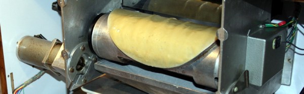
A few years ago [Tweepy], one of the Hackaday readership’s global band of pancake enthusiasts, took possession of an aged “Self-Crêpe” machine. Judging by the look of the date codes on the ICs in the early 1980s, this machine cooked and sold a fresh crêpe on the insertion of a 1 Franc coin (about 17 U.S. cents in those days) for about thirty years.
Sadly, it would no longer produce crêpes. The aged control logic was the culprit, and rather than debug it [Tweepy] decided to replace it with a microcontroller (French language, Google Translate link). The one he chose (marked “RSF2127″, can anyone identify it?) came in a QFP package, so attaching it to a 0.1” prototyping board required some soldering wizardry with fine wires, but it was soon up and running. Some track-cutting and wiring into the original PCB, and the custom C code was ready to go.
The crêpe-making part of the machine features a heated roller not unlike the one in our recently featured South African endless pancake machine in whose comment thread [Tweepy] mentioned it, but appears to use only a single-sided cooking process. The roller has a round crêpe-sized raised area. To start the cooking process, a loading bath of batter is brought up under the roller which is then rotated so that the round raised area passes through the surface of the batter. As the roller turns, it cooks the crêpe, which is then diverted from the roller to the output chute. The whole process relies on a reservoir of pre-made batter, sadly it’s not a crêpe replicator. On the other hand, a single crêpe takes about 40 seconds to create, and the machine can produce them on a continuous basis as long as you keep it stocked with batter.
We like the crêpes, we like the machine, and we like what [Tweepy] has done with it. If any of these machines made it beyond the borders of France, we’ve never seen one in our corners of the Anglophone world. This is a shame, for who wouldn’t want one of those next to the kettle and microwave oven in their hackspace! They would have needed to work on that name, though, for the English-speaking market.
If you’ve worked with steel or iron, you will be very familiar with rust. You will have an impressive armoury of wire brushes and chemicals to deal with it, and your sandblasting guy is probably in your speed-dial list.
We’ve had more than one Hackaday reader contact us of late with videos showing an apparently miraculous handheld laser unit effortlessly stripping away rust, and leaving a near-perfect surface with little mess. Can it be real, they ask, is it an internet hoax? After all if you have done battle with the dreaded iron oxide you’ll know there is no miracle fix to the problem, however you deal with it there has traditionally been hard work involved.
So after a bit of research, we find CleanLaser, the German company whose products feature in the videos. Quoting their website: “Powerful, very short, rapid and moving laser pulses produce micro-plasma bursts, shockwaves and thermal pressure resulting in sublimation and ejection of the target material”. So yes, it seems they’re real.
The website is at pains to stress the environmental benefits of the devices over comparable sandblasting or similar technologies, but has very little information on their safety. They are available in power ratings from 12W to 1KW which is a hell of a lot of laser power to be projecting, yet the operators seem only to be wearing goggles. Perhaps this comes back to the “Powerful, very short, rapid and moving” bit in the quote above, is there no point source to sear your retina? Laser experts please enlighten us in the comments.
If you work with metal or grew up in a metalworking business, this machine probably has you salivating. Sadly for hackers and makers though it’s probable that it and ones like it will be out of our price range for quite some time. Still, the prospect of a guy with one in an industrial unit appearing in most towns can’t be too far away, and that can only be a good thing
The video shows the machine in action. Rusty fire-grate in, perfect shiny surface out. Perhaps only those of you who have spent many hours with a wire brush will understand.