What’s Cooler Than A 7-Segment Display? A 7200-Segment Display!

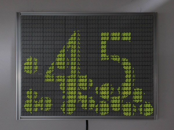
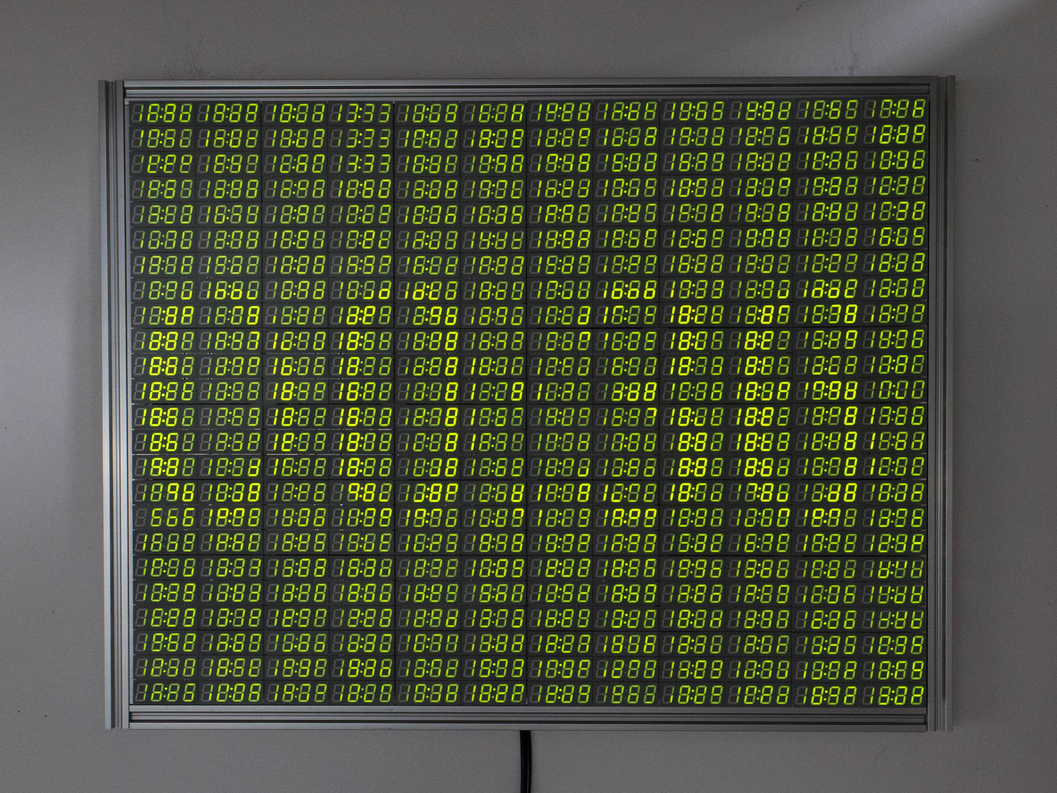
If you look around your desk right now, odds are you’ll see a 7-segment display or two showing you some vital information like the time or today’s weather. But think of how much information you could see with over 1,100 digits, like with [Chris Combs’] 7200-segment display.

For [Chris], this project started the same way that many of our projects start; finding components that were too good of a deal to pass up on. For just “a song or two plus shipping”, he was the proud owner of two boxes of 18:88 7-segment displays, 500 modules in total. Rather than sitting and using up precious shelf space, [Chris] decided to turn them into something fancy he could hang on the wall.

the 7200 segment display grayscaling to show the time
The IS31FL3733 can produce 8 levels of dimming 8-bit PWM, allowing [Chris] to display in grayscale
The first challenge was trying to somehow get a signal to all of the individual segments. Solutions exist for running a handful of displays in one device, but there are certainly no off-the-shelf solutions for this many. Even the possible 16 addresses of the IS31FL3733 driver IC [Chris] chose for this project were not enough, so he had to get creative. Fearing potential capacitance issues with simply using an i2C multiplexer, he instead opted to run 3 different i2C busses off of a Raspberry Pi 4, to interface with all 48 controllers.

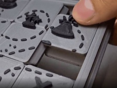
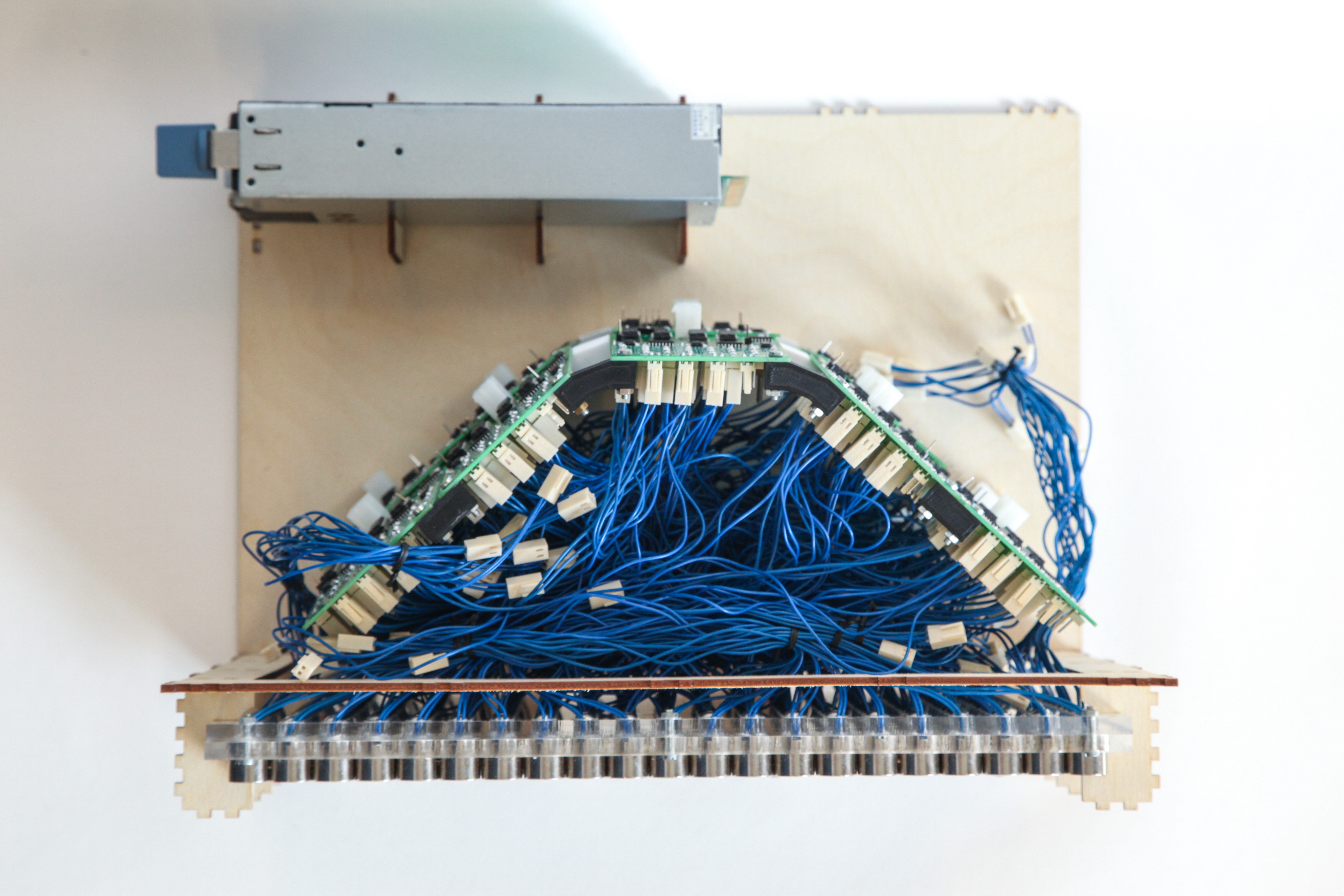
The second challenge was how to actually wire everything up. The finished display comes out to 26 inches across by 20.5 inches tall, much too large for a single PCB. Instead, [Chris] opted to design a series of self-contained panels, each with 6 of the display modules and an IS31FL3733 to drive them. While the multiplexing arrangement did leave space for more segments on each panel, he opted to go for this arrangement as it resulted in a nice, clean, 4:3 aspect ratio for the final display.

The end result was a unique and beautiful piece, which Chris titled “One-to-Many”. He uses it to display imagery and art related to the inevitability of automation, machines replacing humans, and other “nice heartwarming stuff like that”, as he puts it. There’a video after the break, but if you are interested in seeing the display for yourself, it will be on display at the VisArt’s Concourse Gallery in Rockville, MD from September 3 to October 17, 2021. More info on [Chris’s] website.

This isn’t [Chris’s] first adventure in using 7-segment displays in such a unique way, click here to read about the predecessor to this project that we covered last year.

Continue reading “What’s Cooler Than A 7-Segment Display? A 7200-Segment Display!”

the 3 needle ammeters that make up the face of the clock

IC Clock Uses Ammeters For A Unique Time-Telling Display

It is a rite of passage for hackers to make a clock out of traditionally not-clock items. Whether it be blinking LEDs or servos to move the hands, we have all crafted our own ways of knowing when it currently is. [SIrawit] takes a new approach to this, by using ammeters to tell the time.

The clock is built using mostly CMOS ICs. A CD4060 generates the 1HZ clock signal, which is then passed to parallel counters to keep track of the hours, minutes, and seconds. [SIrawit] decided to keep the ammeters functioning as intended, rather than replacing the internals and just keeping the needle and face. To convert the digital signal to a varying current, he used a series of MOSFETs connected in parallel to the low side of the ammeters, with different sizes of current-limiting resistors. By sizing these resistors properly, precise movement of the needle could be achieved by turning on or off the MOSFETs. You can see the schematics and learn more about how this is achieved on the project’s GitHub page (at the time of writing, the most recent commits are in the ‘pcb’ branch).

In addition to the custom PCB that holds all the electronics, PCBs help make up the case as well. While the main body of the case is made out of a repurposed junction box, [SIrawit] had a PCB on an aluminum substrate manufactured for the front panel. While the board has no actual traces or electrical significance, this makes for a cheap and easy way to get a precisely cut piece of aluminum for your projects, with a sharp-looking white solder mask to boot.

We love to see cool and unique ways to tell the time, such as using Nixie Tubes to spell out the time in binary!

Continue reading “IC Clock Uses Ammeters For A Unique Time-Telling Display”

the introduction page of "a summary of electronics"

This Electronics Overview Guides New Hackers In The Right Direction

Many of us don’t have a formal background to build off when taking on new hacks, we have had to teach ourselves complex concepts and learn by doing (or more commonly, by failing). To help new hackers get off the ground a bit easier, [PhilosopherFar3847] created a fantastic starter’s resource on electronics, The Electroagenda Summary of Electronics.

[PhilosipherFar3847] created Electroagenda with the goal of helping amateurs, students, and professionals alike better understand electronics. The Summary of Electronics, one of the more recent additions to the website, is split across 26 sections each breaking down a different electrical concept into easy-to-understand facts with no math or unfamiliar jargon. The summary covers a broad range of electronics, from simple passive components and their uses, up to the basic operating concepts of a microcontroller.

While this resource on its own will not be enough to get a fledgling hacker started making cool circuits, it does provide a very important skill; knowing how to ask the right questions. This base of knowledge provides enough context and keywords to better articulate a challenge and Google-fu a bit more effectively.

Are you the aforementioned fledgling hacker, looking to learn more? check out these nifty logic gates you can plug into each other to build a basic circuit.

[via r/diyelectronics]

an image of the mechanism used to move the curtains

Clever Mechanism Easily Automates Pulling The Blinds

There are few things that we all can agree we hate, and the shrill of your alarm clock waking you from a wonderful slumber is definitely high on that list. To wake up more naturally, [nutstobutts] created an automated curtain opener.

the automated curtain's driving motor

The curtain opener is very simple; a stepper motor in the control box pulls a string, which is run to an idler on the far side of the curtain rod and through two clips, attached to the back of each curtain. This design makes it so that both curtains will open smoothly at the same time, and will always come closed again directly in the center. This design is especially favorable for students in dorms or those that live in an apartment, as the installation requires no screws in the wall or permanent modification to the curtains.

The curtains can be opened and closed either by pressing a button on the control box or by sending HTTP requests to the ESP32 that controls everything. This allows for integration with many different IoT systems, for instance [nutstobutts] has been having Home Assistant open the curtains every morning at 6:30 a.m. in lieu of an alarm clock, and then closing them automatically at 9:00 a.m. to help save on cooling costs.

Automated curtains are a great first IoT project if you are looking to just get your feet wet, check out a different style we covered a few months back for more inspiration!

[via r/functionalprint]

Never Lose A Piece With 3D Printed Sliding Puzzles

Have you ever been about to finish a puzzle, when suddenly you realize there are more holes left than you have pieces? With [Nikolaos’s] 3D printed sliding puzzles, this will be a problem of the past!

An image showing the sliding dovetails of the puzzle
The dovetails, integrated into each piece, keep the puzzle together but still allows pieces to move.

The secret of the puzzle is in the tongue and groove system that captures the pieces while allowing them to slide past each other and along the puzzle’s bezel. The tongues are along the top and right sides of the pieces shown here, with the grooves along the left and bottom. There is only one empty spot on the board, so the player must be methodical in how they move pieces to their final destinations. See this in action in the video after the break.

[Nikolaos] designed the puzzle in Fusion 360, and used this as an opportunity to practice with parameters. He designed the model in such a way that any size puzzle could be generated by changing just 2 variables. Once the puzzle is the proper size, the image is added by importing and extruding an SVG.

Another cool aspect of these puzzles is that they are print-in-place, meaning that when the part is removed from the 3D printer, it is ready to use and fully assembled. No need to remove support material or bolt and glue together multiple components. Print-in-place is useful for more than just puzzles, you could also use this technique to 3D print wire connectors!

Continue reading “Never Lose A Piece With 3D Printed Sliding Puzzles”

Fetch ferrofluid display

Ferrofluid Display Gets New, Better Driver Circuitry

In 2019 [Simen] and [Amud], two students from the University of Oslo, set out to design a unique open-source display. The result was Fetch, a display that uses electromagnets to suspend ferrofluid on 252 “pixels” across the screen. After some delays due to COVID, they have recently unveiled version 2.0 of the display on their project’s page.

While the duo managed to overcome the mechanical challenges associated with using ferrofluids fairly easily, they were quickly bottlenecked by their electronics. The use of electromagnets holding up a liquid presented a unique challenge; the magnets could not be switched off, even for a millisecond, or else the “pixel” would fall down to the bottom of the screen. That immediately ruled out any sort of multiplexing and meant everything would have to be driven in parallel. As if that wasn’t already difficult enough to work around, the effect of having multiple electromagnets activated next to each other would change how the ferrofluid flows. This meant that the strength of each electromagnet would have to be adjusted based on what is currently being displayed, rather than just being on or off.

The mess of connections were not helped with the layout of the old driver boards shown here. The new design puts the connections closer to each individual electromagnet.

All of this, paired with other overhead like generating pulse-width modulation for the inputs, was just too much for a single microcontroller to handle. So, the pair set out to design a better version of their electronics that would offload a lot of the hard work. At the same time, they decided a bit of mechanical optimization was in order; they redesigned the boards to be longer and thinner, allowing them to fit cleanly behind the row of electromagnets they controlled.

The new boards feature a PCA9685 IC, which allows for the control of up to 16 channels of 12-bit PWM over i2C, perfect for the size of the display. Since this IC can’t source enough current to drive the electromagnets, it was paired with a ULN2803 Darlington Transistor Array, capable of delivering up to 500mA to each electromagnet.

With prototypes in hand (and a few bodge wires here and there), [Simen] and [Amud] had the new driver boards running beautifully, displaying text in a mesmerizing way that no ordinary display could match. Watch the video after the break for a demonstration of the new controllers in action, as well as a deeper dive into the process of developing them.

Want to learn more? Check out our previous article about Fetch! Or if you’re looking for another cool way to use ferrofluids, how about making it dance in a custom speaker!

Continue reading “Ferrofluid Display Gets New, Better Driver Circuitry”

mRNA badge next to an image of the actual Moderna vaccine nanoparticle.

Celebrate MRNA Vaccine With This Badge That Blinks The Nucleotide Code

To celebrate getting his second vaccine dose [Paul Klinger] combined two of our favorite things — blinking lights and wearable tech — to create an awesome mRNA vaccine badge.

The badge, which is designed to be worn like a pendant, will slowly blink through all 4,000 nucleotides of the Moderna vaccine over the course of 10 minutes. Watch the video after the break to see it in action. Don’t worry if you got the Pfizer vaccine, you can use the interface button on the back of the badge to change over to Pfizer’s mRNA sequence instead. There’s even a handy legend on the badge, identifying the lipids in case your microbiology skills are a bit rusty.

On the reverse side of the board, you will find a handful of current limiting resistors, a CR2032 battery holder, and the ATtiny1617 microcontroller that runs everything. To assist in converting the mRNA sequence into LED pulses, [Paul] wrote a Python script that will automatically import the nucleotide string from the standard .fasta file and store each nucleotide in just 2 bits, allowing the entire sequence to fit in the program memory of the microcontroller.

This isn’t [Paul’s] first RNA-related project; he originally developed the aforementioned Python script to compress the entirety of the COVID-19 sequence, containing over 30,000 nucleotides, into program memory for his Virus Blinky project, that we featured last year.

Continue reading “Celebrate MRNA Vaccine With This Badge That Blinks The Nucleotide Code”