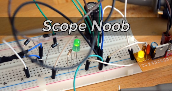
Welcome back to this week’s installment of Scope Noob where I’m sharing my experiences learning to use my first oscilloscope. Last week I started out measuring mains frequency using an AC-AC wall wart adapter. Homework, for those following along, was to build a bridge rectifier and probe the signals from it. Let’s take a look.
Author: Mike Szczys6403 Articles
Astrophotography And Data-Analysis Sense Exoplanets
[David Schneider] was reading about recent discoveries of exoplanets. Simply put these are planets orbiting stars other than the sun. The rigs used by the research scientists include massive telescopes, but the fact that they’re using CCD sensors led [David] to wonder if a version of this could be done on the cheap in the backyard. The answer is yes. By capturing and processing data from a barn door tracker he was able to verify a known exoplanet.
Barn Door trackers are devices used to move a camera to compensate for the turning of the earth. This is necessary when taking images throughout the night, as the stars will not remain “stationary” to the camera’s frame without it. The good news is that they’re simple to build, we’ve seen a few over the years.
Other than having to wait until his part of the earth was pointed in the correct direction (on a clear night) at the same time as an exoplanet transit, [David] was ready to harvest all the data he needed. This part gets interesting really quickly. The camera needed to catch the planet passing in between the earth and the star it revolves around (called a transit). The data to prove this happened is really subtle. To uncover it [David] needed to control the data set for atmospheric changes by referencing several other stars. From there he focused on the data for the transit target and compared points across the entire set of captured images. The result is a dip in brightness that matches the specifications of the original discovery.
[David] explains the entire process in the clip after the break.
Continue reading “Astrophotography And Data-Analysis Sense Exoplanets”
Modular Multicopter Core Flies In Multiple Orientations
[Ioannis Kedros] claims to be rather new to the game of building multi-rotor drones. You’d never know it looking at his latest creation. Yes, we’re talking about the quadcopter seen here, but it’s the core of the machine that’s so interesting. He came up with a PCB hub that allows multiple orientations to be used with the same board. These include tri-copter, and quadcopter with different strut angles for different applications.
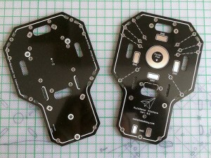 The silk screen of the PCB has dotted lines showing the different angles possible for one pair of motor supports. One set makes a perfect “X” for traditional quadcopter flight. Another reduces the angle between front and back struts for higher-performance quad flight, while the last set is intended for a tricopter setup.
We’d recommend taking a look at [Ioannis’] project writeup whether this particular application interests you or not. His design techniques go through all possible manner of checks before placing the PCB order. There is no substitute for this process if you want to avoid getting burnt by silly mistakes.
Continue reading “Modular Multicopter Core Flies In Multiple Orientations”
Jaw-Dropping Atomic Clock Build
You could cruise the Internet bazaars for a talking clock but you’ll never find one as awesome as this. Just look at it… even if it didn’t work it would be awesome.
[Art] certainly lives up to his username. His Rubidium-standard atomic real-time clock is surely an example of hardware art. The substrate is a collection of point-to-point soldered perfboard modules. Each laid out meticulously. What does such layout call for? A gorgeous enclosure which doesn’t obscure your view of the components. For this he went with a copper tube frame and a custom fabricated aluminum chassis pan.
For the circuit itself [Art] tells us he wanted to build something akin to the old HP nixie frequency counters so he went with logic chips. The pictures and a few video annotations are the only clues we have for how this works. Hopefully your encouragement in the comments will help prompt him to share more about that.
Oh, and the talking clock part that we referred to earlier? Every minute you get a readout of the time thanks to a PIC playing back audio using [Roman Black’s] BTc sound compression algorithm.
Keep Tabs On Passing Jets With Pi And SDR
Obviously Software Defined Radio is pretty cool. For a lot of hackers you just need the right project to get you into it. Submitted for your approval is just that project. [Simon Aubury] has been using a Raspberry Pi and SDR to record video of planes passing overhead. The components are cheap and most places have planes passing by; this just might be the perfect project.
We’re not just talking static frames with planes passing through them, oh no. Simon used two hobby servos and some brackets to gimbal his Pi camera board. A DVB dongle allows the rig to listen in on the Automatic Dependent Surveillance Broadcast (ADS-B) coming from the planes. This system is mandated for most commercial aircraft (deadlines for implementation vary). ADS-B consists of positioning data being broadcast from planes using known frequencies and protocols. Once [Simon] locks onto this data he can accomplish a lot, like keeping the plane in the center of the video, establishing which flight is being recorded, and automatically uploading the footage. With such a marvelously executed build we’re certain we will see more people giving it a try.
[Simon] did a great job with the writeup too. Not only did he include a tl;dr, but drilled down through a project summary and right to the gritty details. Well done documentation is itself worth celebrating!
Continue reading “Keep Tabs On Passing Jets With Pi And SDR”
Scope Noob: Probing Alternating Current
I finally did it. After years of wanting one (and pushing off projects because I didn’t have one) I finally bought an oscilloscope. Over the years I read and watched a ton of content about how to use a scope, you’d think I would know what I’m doing. Turns out that, like anything, hands-on time with an oscilloscope quickly highlighted the gaping holes in my knowledge. And so we begin this recurring column called Scope Noob. Each installment will focus on a different oscilloscope-related topic. This week it’s measuring a test signal and probing Alternating Current.
Measuring a Signal
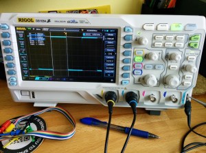
Hey, measuring signals is what oscilloscopes are all about, right? My very first measurement was, of course, the calibration signal built into the scope. As [Chris Meyer] at Sector67 hackerspace here in Madison put it, you want to make sure you can probe a known signal before venturing into the unknown.
In this case I’m using channel 2. Everything on this scope is color-coded, so the CH2 probe has blue rings on it, the probe jack has a blue channel label, and the trace drawn on the screen is seen in blue. I’m off to a fantastic start!
This scope, a Rigol 1054z, comes with an “auto” button which will detect the signal and adjust the divisions so that the waveform is centered on the display. To me this feels like a shortcut so I made sure to do all of this manually. I started with the “trigger” which is a voltage threshold at which the signal will be displayed on the screen. The menu button brings up options that will let you choose which channel to use as trigger. From there it was just a matter of adjusting the horizontal and vertical resolution and position before using the “cursor” function to measure the wave’s voltage and time.
I played around with the scope a bit more, measuring some PWM signals from a microcontroller. But you want to branch out. Because I don’t have a proper signal generator, the next logical thing to measure is alternating current in my home’s electrical system. I suppose you could call it a built-in sine wave source.
Probing Alternating Current
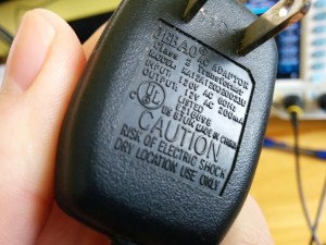
I sometimes take criticism for never throwing things away. Seven years ago we had a cat water fountain whose motor seized. It was powered by a 12V AC to AC converter seen here. Yep, I kept it and was somehow able to find it again for this project.
Of course at the time I thought I would build a clock that measures mains frequency to keep accurate time. This would have done the trick had I followed through. But for now I’m using it to protect me (and my fancy new scope) from accidental shock. I’ll still get the sine wave I’m looking for but with a source that is only 12V at 200 milliamps.
Don’t measure mains directly unless you have a good reason to do so.
Continuing on my adventure I plugged in the wall wart and connected the probe to one of the two wires coming out of it. But wait, what do I do with the probe’s reference clip? I know enough about home electrical to know that one prong of the plug is hot, the other is neutral. The clip itself is basically connected directly to mains ground. Bringing the two together sounds like a really bad idea.
This turns out to be a special case for oscilloscopes, and one that prompted me to think about writing this column. Had this been a 3-prong wall wart, connecting the probe’s reference clip to one of the wires would have been a very bad thing. Many 3-prong wall warts reference the mains earth ground on one of the outputs. If that were the case you could simply leave the clip unconnected as the chassis ground of your scope is already connected to mains ground via its own 3-prong power cord and the reference clip is a dead short to that. If you did need to probe AC using the reference clip you need an isolation transformer for your scope. There are bigger implications when probing a board powered from mains which [Dave Jones] does an excellent job of explaining. Make sure you check out his aptly named video: How NOT to blow up your oscilloscope.
As I understand it, and I hope you’ll weigh in with a comment below, since the wall wart I’m using has a transformer and no ground plug I’m fine using the ground clip of the probe in this case. Even though I’m clipping it to an AC line, the transformer prevents any kind of short between hot/neutral mains and earth ground (via the probe’s ground clip). What I don’t understand is why it’s okay to connect the transformed side of the 12V AC to mains ground?
At any rate, the screenshots above show my progress through this measurement. I first connected the probe without the ground clip and got the sad-looking trace seen on the left. After conferring with both [Adam Fabio] and [Bil Herd] (who had differing opinions on whether or not I should “float the scope”) I connected the ground clip and was greeted with a beautifully formed sine wave. I’m calling this a success and putting a notch in the old bench to remember it by.
What’s Next?
 I don’t want to get too crazy with the first installment of Scope Noob so I’ll be ending here for now. I need your guidance for future installments. What interesting quirks of an oscilloscope should a noob like me explore? What are your own questions about scope use? Leave those below and we’ll try to add them to the lineup in the coming weeks.
Homework
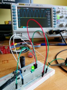
For next week I’m working my way through the adventure of rectifying this 12V AC signal into a smoothed DC source. Here you see a teaser of those experiments. I’ve built a full-wave rectifier using just four diodes (1N4001) and will plunk in a hugely-over-spec’d electrolytic capacitor to do the smoothing. If you want to follow along on the adventure you should dig around your parts drawers for these components and give it a try yourself this week. We’ll compare notes in the next post!
Hackaday Interview: [Grant Imahara]
We had a chance to interview [Grant Imahara] at the 2014 Electronica conference in Munich, Germany. If you don’t recognize [Grant’s] name you’ll probably recognize his face. He’s been on the cast of the television show Mythbusters for about 10 years now. We heard recently that he was leaving the show and that’s how we crossed paths with him.
[Grant] has signed on with Mouser Electronics to promote their Empowering Innovation Together program. They hosted him on a press junket at their booth and since we have a good relationship with Mouser they offered Hackaday an interview slot.
We had a lot of fun talking to [Grant]. Unfortunately the wireless microphones the Mouser videographer was using were picking up a lot of interference. This didn’t directly affect our recording setup as we were using a handheld voice recorder, but we kept getting interrupted as they tried to figure out the problem. Still, as you can see from the video below, we managed to get all the way through a few questions about [Grant’s] introduction to electronics at a young age, his first job out of school working for Industrial Light and Magic, and his advice to others who want to get into electronics and specifically robots. He mentions his early learning was guided by the books of Forrest Mims and that these days learning about electronics is no more than a keyword search away.

