Birth Of An Arduino

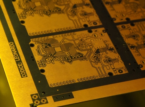
Hey look, an Arduino without its clothes on. This one’s just started its journey to becoming the ubiquitous prototyping tool. The image is from [Bunnie’s] recent tour of the fab house where Arduino boards are made.

As it says on every true Arduino board, they’re made in Italy. [Bunnie’s] trip to the factory happened in Scarmagno, on the outskirts of Torino. The process starts with large sheets of FR4 copper clad material, usually about 1 by 1.5 meters in size. The first task is to send the sheets through a CNC drill. With all of the holes done it’s time for some etch resist; the image above is just after the resist has been applied. A robotic system takes over from here, running the panels through the chemicals which first etch away the copper, then remove the resist and plate the remaining traces. From there it’s off to another machine for solder mask and silk screen.

There are videos of each step available. But our favorite piece is the image at the end that shows a pallet with stacks of completed PCB panels which are headed off to be populated with components.

[via Reddit]

LEGO ROV Without A Tether

[Brane] built an underwater ROV from LEGO mindstorm parts. Look closely at this image and you should notice something missing. The tether that normally carries power and control lines from an ROV to the surface is missing. This is a wireless solution that lets him control the device using an Xbox controller.

The video after the break shows about five minutes of test drive footage. [Brane] has a big aquarium in which he can test the thing. Since he put it together as his senior engineering project at University it’s likely that this is a testing facility at the school. Here’s the little we know about the hardware: It’s using NXT Mindstorm parts to control the motors, with a sealed chamber for a battery. Connectivity is provided by an XBee module with an NXT adapter board called the NXTBee. A laptop with its own XBee module makes up the other end of communications. Right now [Brane] uses an Xbox controller connected to the laptop, but a standalone device would be easy to build by hacking the XBee and controller together directly.

Continue reading “LEGO ROV Without A Tether”

Building A Giant Game Of Life Spinner

We see a lot of projects related to Conway’s Game of Life, but this one is Hasbro’s Game of Life. The board game company recently commissioned a giant game spinner as part of a museum exhibit. Here’s the build log that shows how it was pulled off.

The first thing to note is that [Jzzsxm] does this for a living. His company was hired to build several exhibits related to board games for a children’s museum in Springfield, MA. But don’t let that stop you from offering to help at your own local museum. We know some hackers love doing that kind of work.

The scale of the project is what makes the build really interesting. It starts with a design which can be cut out with a CNC router. First the spinner frame and numbers are cut out of MDF to verify the code. From there the design is cut in two pieces out of HI-MACS, a durable solid-surface material. Pegs for spinning the dial are milled from more HI-MACS stock. The clicker mechanism uses a steel rod as a pivot point. On the underside of the table it has opposing springs to hold it in place no matter which way the thing is spun. [Jzzsxm] mentions that it sees a lot of abuse from the young patrons, but seems to be holding up just great!

[via Reddit]

Back Up The Band With Some RGB Stage Lights

Fresh off the 72-hour madness of the Red Bull Creation contest some of the folks a North Street Labs took on a stage lighting project. It’s for a local performing venue that just opened up, and despite the time crunch the team pulled off another great build.

Sixteen meters of LED strip make the electronics for the project a whole lot easier. The strips run up the center of a cabinets built as stand-alone columns which will end up at the back of the stage. Each cabinet has its own 5V 4A power supply (note the burnout issues they mention when using cheap eBay PSUs). Each column has its own Arduino Uno driving the LEDs, with an RS485 shield to connect back to a main Arduino Mega 2560 controller. It uses a PSX controller to switch between different lighting modes.

The seven towers boasting 688 LEDs isn’t all that’s shedding light on the show. There’s also about 300 feet of EL wire at work.

Continue reading “Back Up The Band With Some RGB Stage Lights”

Robot Servo Control Using Smartphone Audio Jack

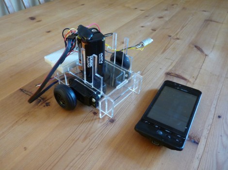
[Jim] has an old Android phone he’d like to use as a Robot brain. It’s got a lot of the things you’d want in a robot platform; WiFi, Bluetooth, a camera, an accelerometer, etc. But he needed some way to make the mobile, mobile. What he came up with is a chassis with servos that can be controlled by the phone’s audio port.

To start his adventure he crafted a square wave audio file in Audacity and then played it back on the Android music player. By monitoring the output on an oscilloscope he found the wave was well produced, with peaks of about 1V. With that in mind he designed a circuit using two transistors to amplify the signal, thereby creating a usable input for the servo motors. Each motor has one of these circuits connected to it, with the left and right channels from the audio jack driving them separately. In the clip after the break you can see he even wrote a simple Android app to extend the idea to a more usable level.

This is a similar technique as used by the recon robot we saw about a year ago.

Continue reading “Robot Servo Control Using Smartphone Audio Jack”

How To Design Your Own LED Driver

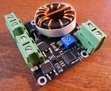
If you find yourself in need of a driver for a high power string of LEDs this is a must read. [Limpkin] just designed this driver as a contract job. He can’t show us the schematic, but he did share some tips on how to build an LED driver around a MAX16834 chip.

As you move to higher power designs the barriers to success pile up rather quickly. Using a chip like the MAX16834 really helps to simplify the task as it can be used as a boost or buck converter, it includes functionality that allows for dimming, and it’s a constant currents solution. There are board design issues that need to be accounted for in these designs. [Limkin] included links to a few calculators that will help you determine trace width based power levels used with the driver. He also recommends using copper pours on both sides of the board connected with vias to help dissipate heat. To that end he used an IR thermometer for feedback during testing.

It’s too bad he doesn’t have any photos of the device at work. If you build something similar please take some pictures and tip us off about it.

Work Station Includes A Smartcard Lock For USB Ports

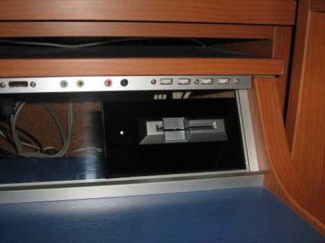
The USB ports on this work station are locked. In order to use a USB device you’ll need to insert a Smartcard into the reader seen above. The interesting thing here is that this shouldn’t affect your ability to charge a USB device. When you visit the link above make sure to check out the worklog tab as it contains nine pages worth of build information.

The device is conceived of in two parts. There is one board which does the USB switching, and another that takes care of the Smartcard reader. That reader is based on a PIC 16F1939. It readers the Smartcard, verifies the data, then controls the USB switching board via SPI. An ADG714 chip completes the circuit on eight data lines making up the four USB ports. There is also a mechanical relay on the board which can cut USB power. Since this is separate from the data switching, the power could be left on for charging or toggled separately by a card that has permission to charge but not to use the data ports. You can see a demonstration of the system embedded after the break.

Continue reading “Work Station Includes A Smartcard Lock For USB Ports”