Homebrew 16-Bit Computer Is A Wire-Wrapped Work Of Art

Breadboard 8-bit computer builds seem all the rage these days, and with good reason: building your own CPU from the board up using discrete logic chips is a great way to really learn how microprocessors work. Not to mention that it’s an incredible flex. But once you’ve conquered the eight-bit, what do you do? Easy: build a 16-bit computer from 74HC logic chips.

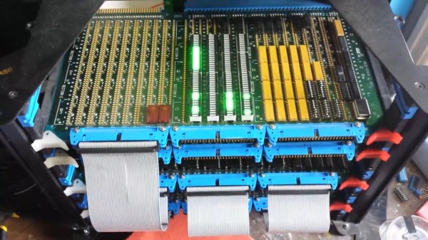
Attentive readers will likely remember this computer’s builder, [Paulo Constantino], from his previous work on 8-bit breadboard computers. As gloriously entropic as that tangled mass of wires was, it must have been a nightmare for [Paulo] to maintain. And so when the time came to upgrade, he wisely chose a more integrated construction method. The construction method is wire-wrapping, with multiple cards plugged into backplane and connected by ribbon cables. The whole card cage is far neater than the previous build, and seems to lend itself to rapid modifications. The top card in the cage acts as a control panel for now; eventually, [Paulo] planes to put a real front panel on the cage to support all the switches and blinkenlights such builds demand. Stretch goals include supporting audio and video and getting the machine online so anyone can log in.

The video below is an overview of the current state of the machine; earlier videos in the playlist cover the design and build in more detail. We hope to see schematics soon, and we’d love to know where to get some of those wire-wrap PCBs for projects of our own.

Continue reading “Homebrew 16-Bit Computer Is A Wire-Wrapped Work Of Art”

[NE555]’s SMD Prototyping Is A Work Of Art

ne555_20yearsold
One of [NE555]’s boards from the 90s.
Over on twitter [NE555] has been posting beautiful SMD prototypes.

Back in the 90s when surface mount components gained widespread adoption, the quick and cheap PCB prototyping services of today were unavailable. This led many to develop their own approaches. In Japan a particularly novel and beautiful approach was, and still is, somewhat popular. [NE555]’s work is a excellent example of this technique using a fine enameled wire (you can find this on eBay as “magnet wire”), wirewrap board, and careful hand soldering. [NE555] has made a great video on the process (which you can watch below).

Continue reading “[NE555]’s SMD Prototyping Is A Work Of Art”

Laser Cutter Exhaust Interlock Is Silly, Educational, Useful

If there’s one maker space that has an excess of mad scientist type hackers, it has to be LVL1 in Louisville, KY. They sure do a lot of crazy stuff, like this simple device to defeat the laser cutter smoke monster. Nobody got the memo about the “simple” part. Instead they created a functional, educational and aesthetically pleasing element for the hackerspace.

LVL1 has a large format laser cutter. Laser cutters emit nasty smoke. Said smoke needs to be vented outside. To do so, it needs to pass through a scrubber/filter so the neighbouring Pigs don’t complain. So they installed a larger, better filter. The Pigs are happy, until the filter gets clogged and the smoke monster decides to escape. Next they install a pressure switch which disables the laser when the filter gets clogged. Laser cutters have a myriad of safety interlocks, so quite often, it isn’t apparent which one caused it to trip. Hence, the Laser Cutter Enable Module – LCEM.

The simple part was to install an indicator that lights up when the pressure switch is enabled, and off when not. But when it’s off, it isn’t clear if the pressure switch is off, or the indicator has failed. Simple, just install a bi-color LED – Red for off, Green for On. But then what about color blind folks who cannot tell the two colors apart? So, finally, two LED’s with clearly labelled text marking them as Enabled and Disabled.

A simple (this time for real) circuit was finally agreed upon. The SPDT contacts of the pressure switch drive the LED in an optoisolator. Its output drives a DPDT relay via a transistor. One set of contacts light up the two indicator LED’s and the other set of contacts goes to the laser cutter enable contacts. Of course, the optoisolator is totally redundant and over kill too – it’s input LED shares the same power supply as the output transistor! Remember the missing memo?

It was time to assemble the circuit. This is where the mad scientist dudes got really creative. On one half of a piece of acrylic, the schematic diagram was etched using the laser. This ensures n00bs get some education. And the remaining half had the circuit laid out in old-skool wire wrap fashion. Holes were drilled and connections were drawn (using the laser, of course) for the various components. Parts were inserted, and wires were soldered to make the connections. The result is what they call the PCB/Mounting Plate/Educational Schematic/Acrylic thing. Of course, exposed connections and wires are no good. So they made a sandwich consisting of a flat acrylic base, and a cut out frame in the middle to accommodate the wire connections and joints. All of this to light up an indicator. Because.

Thanks [JAC_101] from LVL1 for sending in this tip.

If you want to read more about LVL1 shenanigans, check out this post about their Rocketry group, or this post when Hackaday visited LVL1.

Printing Point-to-point Circuits On A 3D Printer

[CarryTheWhat] put up an Instructable on his endeavours in printing circuit boards for solder free electronics. He managed to print a flashlight where the only non-printed parts are a pair of batteries and a couple of LEDs.

The circuit is a weird mix of point to point and Manhattan style circuit construction; after modeling a printed plastic plate, [CarryTheWhat] added a few custom component holders to hold LEDs, batteries, and other tiny electronic bits.

To deliver power to each electronic bit, the components are tied off on blue pegs. These pegs are attached to each other by conductive thread much like wirewrap circuit construction.

Right now, the circuits are extremely simple, but they really remind us of a few vintage ham radio rigs. While this method is most likely too complex to print 3D printer electronics (a much desired and elusive goal), it’s very possible to replicate some of the simpler projects we see on Hackaday.

[CarryTheWhat] put the models and files up on GitHub if you’d like to try out a build of your own.

Processor Built With Transistor-Transistor Logic

cpu-built-from-ttl

[Donn] wanted know exactly what is going on inside of a processor so naturally he built a CPU out of TTL components. He had previously built a couple of versions of a computer based on the Z80 processor. Using the troubleshooting skills he learned and a second-hand textbook, he set to work using 74LS series chips connected using the wire-wrap method we’re familiar with from other cpu projects.

The finished product runs well at 1.8 megahertz, but he also included a 2 hertz clock and a step clock for debugging. At the slower speeds, the register board (seen at the left in the picture above) lights LEDs and can be used to tell what the CPU is currently working on. Programming is accomplished through either  a dumb terminal or a PC running a terminal emulator.

His writeup is from about five years ago but that didn’t prevent us from getting that fuzzy feeling in the geek-center of our brain when we read about it. It is well written and thorough so if you’re into this kind of thing there’s plenty to enjoy.

[Thanks Raleigh]