Control The Air Conditioning With Slack

[Raphael Baron] needed a better way to control his office’s air conditioning units. Sure, they have remotes, but that’s too easy. [Raphael] came up with a solution that uses an ESP8266, a computer, IR LEDs, and a bot that runs on Slack.

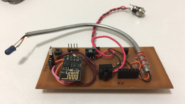
[Raphael] built a prototype of the ESP8266 hardware on protoboard and used it to read and record the IR signals from the remote. Once he’d figured out the issues he was having with the IR library he was using, he could use it to send the IR commands to the AC unit. Since their office has two AC units, [Raphael] built a second prototype which had two IR LEDs but didn’t have the IR receiver. Using this he could turn both AC units on and off and set their temperatures.

For the server, [Raphael] turned to Clojure, a dialect of Lisp, which provides easy access to the Java Framework, mainly to get practice working with the language. The server’s main responsibility is to use Slack’s real-time API to listen for messages from a Slack bot and forward them to the ESP. In this way, a user talking to the Slack bot can send it messages which the server forwards to the microcontroller which, in turn, parses the messages and send IR commands to the AC units.

[Raphael] admits that this isn’t the most advanced, professional stuff, but it doesn’t matter. The schematics for the ESP8266 board and the code for both the ESP board and the server are available on GitHub. There seems to be a lot of hacks using Slack, such as this NERF Turret controlled by a Slack bot.  Or this jukebox that users can interact with by talking to a Slack bot.

Hackaday Prize Entry: E.R.N.I.E. Teaches Robotics And Programming

[Sebastian Goscik]’s entry in the 2017 Hackaday Prize is a line following robot. Well, not really; the end result is a line following robot, but the actual project is about a simple, cheap robot chassis to be used in schools, clubs, and other educational, STEAM education events. Along with the chassis design comes a lesson plan allowing teachers to have a head start when presenting the kit to their students.

The lesson plan is for a line-following robot, but in design is a second lesson – traffic lights which connect to a main base through a bus and work in sync. The idea of these lessons is to be fairly simple and straightforward for both the teachers and the students in order to get them more interested in STEM subjects.

What [Sebastian] noticed about other robot kits was that they were expensive or complicated or lacked tutorials. Some either came pre-assembled or took a long time to assemble. [Sebastian] simplified things – The only things required after the initial assembly of the chassis are: Zip-ties, electrical tape and a few screws. The PCB can’t be disassembled, but the assembled PCB can be reused.

The hardware [Sebastian] came up with consists of some 3mm material that can be laser cut (acrylic or wood) and a sensor board that has 5 IR LEDs and corresponding IR sensors. The chassis can be put together using nothing more than a Phillips screwdriver, and the sensor PCBs are well documented so that soldering them is as easy as possible. An Arduino is used as the brains of the unit.

[Sebastian] has come up with a great project and the idea of a platform like this with a couple of lesson plans included is a great one. He’s released the hardware under an Open Hardware license as well so others can share and add-on. Of course, there are other line following robots, like this miniature one created with analog circuitry, and there are other open source robots for teaching, like this one. But [Sebastian]’s focus on the lesson plans is a really unique way of approaching the problem – one that will hopefully be very successful.

Continue reading “Hackaday Prize Entry: E.R.N.I.E. Teaches Robotics And Programming”

How To Eclipse When All You Have Is A Welding Helmet

What do you do if you don’t trust cheap eclipse-watching glasses from the internet? What about if everyone’s sold out? Well, if you want to watch the eclipse and you have an auto-darkening welding helmet, you can do what [daniel_reetz] did and hack something together with a remote and your welding helmet to let you see the eclipse without blinding yourself.

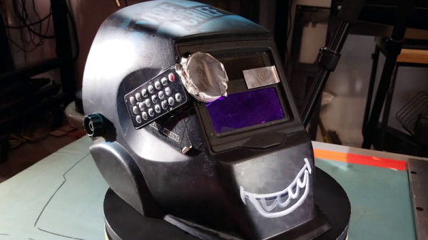
Essentially, the hack tricks the helmet’s sensors into thinking it’s very bright. [Daniel_reetz] accomplishes this by gluing a remote with an infrared LED to the side of the helmet and covering it with a 50mm plastic lid. There are two sensors on [daniel_reetz]’s helmet, so he covers the other one with aluminum tape. What this means is that when he presses a button on the remote, the lid-covered sensor thinks it’s very bright out and since the other sensor is covered, it darkens the lens of the mask.

I’m sure some of our readers could come up with a more sophisticated method that would allow you to do something other with your hand than press the remote buttons, but this is a quick and easy hack that’ll get you able to take a quick look at the eclipse – assuming you have a welding mask capable of shading to level 13 or 14. If you are hoping to catch a glimpse of the eclipse, check out the safety guide from NASA just to make sure your eyes are safe. For another method of viewing the eclipse, check out this wearable pinhole camera. For another welding mask hack, check out this augmented reality mask.

Continue reading “How To Eclipse When All You Have Is A Welding Helmet”

Use A Drill To Power Your Flipbooks

[WolfCat] of Wolfcatworkshop is creating a hand-animated split-flap animation. But what do you use to test your animation once it’s on the split-flaps? Well, to test it out, [WolfCat] used a drill to give it motion. DoodlersAnonymous has some pics and an interview with [WolfCat] about his animation and there are some pictures on his Instagram page.

Technically, what [WolfCat] wanted to make is a “mutoscope,” a hand-cranked precursor to the movie projector that had its heyday in the late 19th and early 20th century. Originally installed in penny arcades and the like, mutoscopes were single-viewer apparatus. The viewer cranks the handle and the animated cards inside rotate around, stopped briefly by a bit of metal at the top in order to show a frame. The basic idea is similar to the way split-flap clocks or signs work.

[WolfCat] hand drew the animation for his movie and then scanned and printed out each frame. The frames were then transferred to a pair of flaps. [WolfCat] wanted to see how it would look when animated, but didn’t have any plans at the time for a case or a hand crank, so he found the closest tool that would do the job – a cordless drill. Attaching the drill and using a bit of card or wood as a stopper, [WolfCat] could see how the end result would look and could then start work on the case and crank.

The drill is a quick and easy way to see what the finished product would look like. Once he’s got it working, [WolfCat] could check out this 3D printed mutoscope case, or this flip dot animated display.

Continue reading “Use A Drill To Power Your Flipbooks”

We Should Stop Here, It’s Bat Country!

[Roland Meertens] has a bat detector, or rather, he has a device that can record ultrasound – the type of sound that bats use to echolocate. What he wants is a bat detector. When he discovered bats living behind his house, he set to work creating a program that would use his recorder to detect when bats were around.

[Roland]’s workflow consists of breaking up a recording from his backyard into one second clips, loading them in to a Python program and running some machine learning code to determine whether the clip is a recording of a bat or not and using this to determine the number of bats flying around. He uses several Python libraries to do this including Tensorflow and LibROSA.

The Python code breaks each one second clip into twenty-two parts. For each part, he determines the max, min, mean, standard deviation, and max-min of the sample – if multiple parts of the signal have certain features (such as a high standard deviation), then the software has detected a bat call. Armed with this, [Roland] turned his head to the machine learning so that he could offload the work of detecting the bats. Again, he turned to Python and the Keras library.

With a 95% success rate, [Roland] now has a bat detector! One that works pretty well, too. For more on detecting bats and machine learning, check out the bat detector in this list of ultrasonic projects and check out this IDE for working with Tensorflow and machine learning.

DIY VT220 Keyboard

There’s always been interest in the computers of old, and people love collecting and restoring them. When [peterbjornx] got his hands on a DEC VT220 video terminal, it was in good shape – it needed a bit of cleaning, but it also needed a keyboard. [Peter] couldn’t afford to buy the keyboard, but the service manual for it was available, so he decided to convert a modern keyboard to work with his new terminal. (Editor’s note: Link rot. Try the Internet Archive’s Wayback Machine link instead.)

The original keyboard for the VT220 is the LK201. This keyboard communicates with the terminal using 8-N-1 (eight data bits, no parity, one stop bit) over RS232 at 4800 baud. This meant that it would be pretty simple to implement this on microcontroller in order to communicate with the terminal. [Peter] chose the Arduino Nano. However, the LK200 was more than just a keyboard for communicating with the terminal, it also housed a speaker and LEDs which the terminal used to communicate with the user. Rather than put these into the adapter unit, [Peter] decided to put these into the keyboard – a few holes and a bit of wiring, and they were in.

[Peter]’s write-up includes a description of some of the issues he encountered as well as a picture of the keyboard. He’s put the schematic online and the code up on GitHub. In case you were wondering, he used Vim on the VT220 to write his article. You could also use a Raspberry Pi to help out your dumb terminal, or just hook the terminal directly to your Linux box and go from there.

Raspberry Pi Tracks Office Happiness

It’s always great to see people who haven’t had the opportunity to work with hardware like the Raspberry Pi before come up with a great project and have fun putting it together.  [Katja]’s company has a two-day hackfest where employees can work on some cool non-work-related projects. [Katja]’s team decided to use a Raspberry Pi and some buttons and LEDs to create a ‘happiness tracker‘ for the company.

The resulting project is mounted near the entrance to the office and when they come in or leave, an employee can push one of four buttons to indicate their mood at the time, ‘bad,’ ‘not so good,’ ‘good’ or ‘super.’ The result is tracked and an overall impression of the office’s happiness is the result.

The project consists of the aforementioned Raspberry Pi, four push buttons, five LEDs that animate when a button is pressed and another LED that shows the system is currently up and working. When a user presses a button, the five LEDs animate in the shape of a check mark to show that the button press was successful. A Python script running at startup on the Pi takes care of detecting button pressing, lighting LEDs and sending a message to the server which monitors the level of happiness.

It’s a simple project, but that’s exactly what you need when you start with hardware you haven’t worked with before. It seems like [Katja]’s team had fun building the project and they hope that this can help gauge the overall wellbeing of the office. [Katja]’s blog post has an embedded video of the project in action. In the meantime, check out this bit of facial recognition software that determines how happy you are based on your smile, or this project that lets you know how happy your plant is.