A camera slider made from wood and recycled parts

Turning Old Plotter Parts Into A Smooth Camera Slider

Taking apart old stuff and re-using the parts to make something new is how many hackers first got started in the world of mechanical and electronic engineering. But even after years working in industry we still get that tinge of excitement whenever someone offers us an old device “for parts”, and immediately begin to imagine the things we could build with the components inside.

A GoPro mounted on a moving platform made from recycled partsSo when [Victor Frost] was offered an old Cricut cutting plotter, he realized he could use its parts to create the camera slider he’d been planning to build. The plotter’s X stage, controlled by a stepper motor, was ideal for moving a camera platform back and forth. [Victor] wanted to build the entire thing in a “freehand” way, without making a detailed design or purchasing any new parts. So he dived into his parts bin and dug up an Arduino, a 16×2 LCD, some wires and buttons, and a few pieces of MDF.

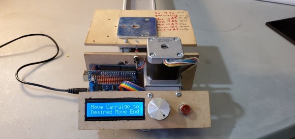
The camera mount is simply a piece of steel that a GoPro’s magnetic mount can latch onto, but [Victor] keeps open the possibility of mounting a proper tripod ball head. The Arduino drives the stepper motor through an Adafruit Motor Shield, with a simple user interface running on the LCD. The user can set the desired end points and speed, and then run the camera back and forth as often as needed. In this way, the software follows the same “keep it simple” philosophy as the hardware design.

If you’re planning to build your own camera slider, [Victor]’s design should be easy to copy, if you happen to have an old cutting plotter. If not, you can try this simple yet well-engineered model. Want even more? Then check out this fancy multi-axis camera motion control rig.

Continue reading “Turning Old Plotter Parts Into A Smooth Camera Slider”

A clock made with LED filaments inside clear plastic tubes

LED Filaments Make A Retro Clock Without Any Retro Parts

We love clock projects here at Hackaday, and we’ve seen many beautiful designs based on a wide variety of display technologies. There are various types of glass tubes like Nixies, Numitrons and classic VFD displays, all of which have that warm “retro” glow to them. Then there’s LEDs, which are useful for making cool pixel-based timepieces and easy to drive with low-voltage electronics. So how about combining the best of both worlds, by using LEDs to make a Numitron-like display? That’s exactly what [Jay Hamlin] did when he built a digital clock based on LED filaments.

The heart of the project consists of orange LED filaments similar to the ones used in vintage-style LED light bulbs. [Jay] bought a bunch of them online and tried various ways of combining them into seven-segment displays, eventually settling on a small PCB with a black finish to give good contrast between the LEDs and the background. To make the displays look like they’re encased in glass, [Jay] bought a set of plastic test tubes and cut them to size.

The base of the clock is formed by a slick black PCB that holds an ESP32. The segments are driven through a set of 74LV595 shift registers to keep the required number of GPIOs to a minimum. There are no buttons: thanks to a WiFi connection and the Network Time Protocol the ESP32 automatically keeps the correct time.

The end result looks remarkably like a Numitron display at first glance, and remains a beautifully-made clock even if you notice that there’s no glass to be found. If you’re into LED filament clocks (and who isn’t?), check out this analog wall clock, or this spiderweb-like digital clock.

Continue reading “LED Filaments Make A Retro Clock Without Any Retro Parts”

An NRF24L01 module soldered onto a 6502 single-board computer

Wireless Bootloader Saves You From Swapping ROM Chips

Flashing your code into an Arduino, an ESP32 or any other modern microcontroller platform is pretty straightforward: connect the device through USB, fire up the appropriate software platform, and press “program”. But those who followed embedded programming classes in the ’80s and ’90s will remember a more complicated procedure that consists of swapping EPROM chips between a programmer, a target board and a UV eraser. Veterans of that era might even remember how you could overwrite a previous program with NOPs and place new code behind it, to save yourself a trip to the “blank chips” bin.

If you’re a retrocomputer enthusiast and would like to have the easy programming of modern tools, but the authenticity of a self-contained ROM-loading computer, you might want to check out [Anders Nielsen]’s latest design of a wireless boot loader for a 6502 single board computer. The target platform for this project is a beautiful custom-made 6502-based retrocomputer that [Anders] documented in detail on his Hackaday.io page.

The basic idea here is to have a wireless receiver on the target system that receives data from a transmitter connected to a modern PC. When you click “program”, the object code is sent to the 6502 machine, stored in RAM and executed. The wireless link is implemented with a pair of nRF24L01 2.4 GHz modules that communicate through SPI. Since [Anders]’s Mac Mini doesn’t come with GPIO ports he hooked up the transmitter to a Raspberry Pi which he controlled through a network link.

On the 6502 side he wrote a bootloader in assembly language, which bit-bangs the SPI protocol to communicate with the wireless module. A simple user interface is included to allow the user to control the loading and running of programs. All code and hardware documentation is available on Github for use by anyone with a similar 6502 system.

Those nRF24L01s are versatile little things: we’ve seen them being used to transfer anything from MIDI data to TCP/IP links, as well as code for other microcontroller platforms.

Continue reading “Wireless Bootloader Saves You From Swapping ROM Chips”

A disassembled Game Boy-shaped Hackintosh

This Big 3D-Printed Game Boy Actually Runs MacOS

While mobile gaming has largely moved to smartphones these days, the classic Game Boy remains a hugely popular platform for retro enthusiasts, owing in no small part to its enormous library of quality games. The original Game Boy hardware is pretty much bulletproof, but feels a bit outdated today because it lacks modern conveniences like a large, backlit display or a rechargeable battery.

[iketsj] wanted to build a modern take on the Game Boy design and designed what’s in effect a 3D-printed, oversized copy of the classic handheld powered by a modern single-board computer. Most people would have gone for something obvious like a Raspberry Pi running Linux, but not [Ike]: he decided to go for a LattePanda Alpha board and run macOS Monterey on it. That makes this a Hackintosh, and probably one of the last ones as well since Apple is busy migrating all of its products onto its own proprietary CPUs.

The LattePanda also has an Arduino integrated on its board, which is used to read out the Game Boy’s buttons as well as the resistive touch screen. It communicates with the macOS system through a Python script that emulates mouse movements and keypresses. Sadly, the touch function is not working because [Ike] accidentally damaged the touch-sensitive system while trying to slim down the display module. Still, the seven pushbuttons are more than enough when running a Game Boy emulator, and there’s also a USB connector available to connect external peripherals like a keyboard, mouse or monitor.

We’ve seen several great Game Boy projects over the years: some made from brass, some very wide, and some that stuff modern computing platforms inside an original Game Boy case. Combining a Game Boy with a Hackintosh is definitely a new development, though it matches well with [Ike]’s history of unusual Hackintosh designs. Continue reading “This Big 3D-Printed Game Boy Actually Runs MacOS”

A portable water quality monitor

Monitoring Water Quality Using Lots Of Sensors And Machine Learning

Despite great progress over the past century, more than a billion people still don’t have access to clean drinking water today. Much of the water on Earth’s surface is polluted, but it’s not always easy to tell a dirty stream from a clean one. Professional kit for water analysis can be expensive, which is why [kutluhan_aktar] decided to design a portable, internet-connected water pollution monitor.

A bowl of water with several sensors immersed in it, and a blue box connected to them
Calibrating the system using a bowl of clean water.

There is no single parameter that determines the quality of a water sample, so the pollution monitor has no less than five different sensors. These can determine the oxidation-reduction potential (a chemical indicator), the pH (acidity), total dissolved solids (mainly salts), turbidity (suspended particles) and temperature. To combine all these numbers into a simple “yes/maybe/no” indicator, [kutluhan] trained a neural network with data gathered from a large number of places around his hometown.

This neural network runs on an Arduino MKR GSM 1400 module. While not a typical platform for AI applications, the neural network runs just fine on it thanks to the Neuton framework, a software plaform designed to run machine learning applications on microcontroller systems like the Arduino. It also has a GSM/3G modem, allowing it to report the measured water quality to a central database.

All of this is housed in a 3D-printed enclosure that makes the whole setup easy to carry and operate in any location. Collecting data across a wide area should help to locate sources of pollution, and hopefully contribute to an improvement in water quality for everyone. Here at Hackaday we love citizen science initiatives like this: previously we’ve featured projects to measure things as varied as air quality and ocean waves.

The insides of a tube-based noise source

Using A Vacuum Diode To Make The Cleanest Noise Source You’ve Ever Seen

Noise is an annoying but unavoidable part of any engineering project. Fixing noise issues is hard enough, but even just measuring how much noise an amplifier adds to your signal is tricky without proper equipment like a spectrum analyzer. One other thing that makes noise measurements easier is a good, stable noise source that can serve as a reference: you first measure your amplifier without any input, and then measure it again with the noise source connected. Using a few simple formulas you can then calculate how much noise the amplifier produced.

Building a source that generates exactly the amount of noise that you want, no more and no less, is quite a challenge in itself. Several techniques exist, but [Wolfgang] over at the Electronic Projects for Fun blog decided to go for the classic method of using a vacuum diode. He describes the design and analysis of a noise source based on a 2D3B tube in a detailed article.

The tube in question is a special vacuum diode designed to be operated in saturation, meaning at a current high enough to draw away all the electrons generated by the hot filament. When running in this mode, the output current has a noise spectrum that is almost perfectly white, meaning its power level remains constant across the frequency band. [Wolfgang]’s measurements show a deviation of no more than 0.2 dB between 200 kHz and 200 MHz. This is about as close to perfect as you can get, and covers most of the frequency bands of interest to radio amateurs.

The whole project is built up inside a sturdy metal box, with extensive shielding and line filtering to keep undesired signals from contaminating the clean noise signal. A limiter is also an essential component: should the diode’s filament break, the limiter will prevent the sudden transient from reaching the spectrum analyzer and destroying its (very expensive) input stage.

[Wolfgang] has made a few other noise sources based on various components, which he compares on a separate page, although the 2D3B based one is by far the most stable. We’ve also featured a simple pink noise source, which is useful for audio measurement, as well as white noise sources designed to generate random numbers or simply to help you sleep.

A vintage watch with a new PCB inside, next to a 3D rendered image of the PCB

Modern, Frugal PCB Breathes New Life Into Soviet-Made LED Watch

The first electronic digital watches were admired for their pioneering technology, if not their everyday practicality, when they were introduced in the 1970s. Their power-hungry LED displays lit up only when you pressed a button, and even then the numbers shown were tiny. Their cases were large and heavy, and they drained their batteries rather quickly even when not displaying the time. Still, the deep red glow of their displays gave them a certain aesthetic that’s hard to replicate with today’s technology.

A vintage LED watch displaying "16.42"
Pressing the top-right button enables those beautiful LED modules

When [Benjamin Sølberg] got his hands on an Elektronika-1, a first-generation digital watch designed in the Soviet Union, he set about designing a modern replacement for its internals. Where the original had several custom chips wire-bonded directly onto a substrate, the new board contains an MSP430 series microcontroller as well as an AS1115 display driver. The PCB makes contact with the watch’s pushbuttons through clever use of castellated holes.

For the display [Benjamin] went with period-correct LED modules made by HP, which keep the display’s appearance as close to the original as possible. While these draw quite a bit of current, the rest of the watch has become an order of magnitude more frugal: the stand-by time is now estimated to be about ten years, where the old design often needed new batteries within a year. [Benjamin] uses his renovated watch on a daily basis, apparently without trouble.

If you’ve got an old Soviet digital watch that you’d like to upgrade, you’ll be pleased to hear that the entire design is open source. Just like this retro watch, in fact, that uses a similar LED display. If you’re into original vintage watches, we’ve covered them in depth, too.