Digital Microscope With An On-Screen Multimeter

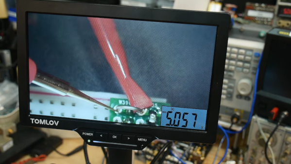
Some things go together, like chocolate and peanut butter. Others are more odd pairings, like bananas and bacon. We aren’t sure which category to put [IMSAI Guy]’s latest find in. He has a microscope with a built-in digital multimeter. You can see the video of the device in operation below.

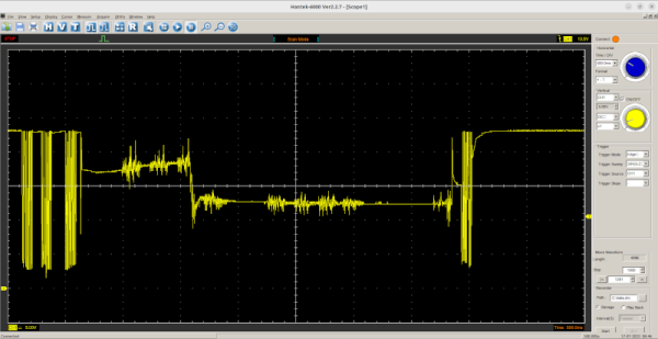
The microscope itself is one of those unremarkable ten-inch LCD screens with some lights and a USB camera. But it also has jacks for test probes, and the display shows up in the corner of the screen. It is a normal enough digital meter except for the fact that its display is on the screen.

If you had to document test results, this might be just the ticket. If you are probing tiny little SMD parts under the scope, you may find it useful, too, so you don’t have to look away from what you are working on when you want to take a measurement. Although for that, you could probably just have a normal display in the bezel, and it would be just as useful.

At about $180 USD, it’s not exactly an impulse buy. We wonder if we’ll someday see an oscilloscope microscope. That might be something. These cheap microscopes are often just webcams with additional optics. You can do the same thing with your phone. If you don’t need the microscope, but you like the idea, can we interest you in a heads-up meter?

Continue reading “Digital Microscope With An On-Screen Multimeter”

Tesla Door Phone Decoded (Not That Tesla)

[Danman] has digital door phones manufactured by Tesla — or at least, a Tesla, as they’re not to be confused with the carmaker, though. The problem is if someone comes to the door when no one’s home, there’s no remote indicator. The answer? Reverse engineer the protocol and fix it.

A quick dump on a storage scope showed the data clearly, but it wasn’t obvious what protocol it was using. After a little analysis, it proved the datastream used 4 PWM pulses as symbols with three symbols: one, zero, and stuffing sequence.

Once you can read the bits, it is easy to determine that each frame consists of a 16-bit destination and source address, along with a command byte and a checksum byte. Each station can have an ID from 000 to 999 although you can only dial up to number 323. Some nodes are special, and there are ways to address particular units.

Connecting to the hardware took a transformer for isolation. Honestly, unless you have this exact hardware, this isn’t likely to be something you can directly use. However, it is a great example of how you can figure out a specialized device and bend it to your will.

We love reverse engineering projects. In some cases, it is easier if you have a CT scan.

Practical Inductors In LTSpice

LTSpice and the underlying Spice engine does a great job of simulating ideal components. But it is also capable — if you know how — of handling models of real-world devices. Inductors, for example, are one of the most imperfect components. Their constituent wire has resistance, and there is parasitic capacitance between the windings. If there is a core, it also will have many imperfections and losses. [Sam Ben-Yaakov] has a lecture about modeling real inductors in LTSpice, and he covers how you can capture some of these imperfections in the video below.

There is a bit of math in the presentation, but we liked that it relates back to datasheets for actual components. Being able to understand what the parameters on a datasheet mean is crucial, and if you ever wondered what some of these entries mean, you’ll get a lot from this video.

The main feature of the model is the flux equation. The tanh (hyperbolic tangent) function is similar to the curve you want for the flux equation, so it plays a major part. Of course, there are other parts of the inductor you may have to model, too, but this is one of the most difficult parts.

You can also model transformers using LTSpice. You can also create custom components.

Continue reading “Practical Inductors In LTSpice”

Finding Undocumented 8086 Instructions Via Microcode

Video gamers know about cheat codes, but assembly language programmers are often in search of undocumented instructions. One way to find them is to map out all of a CPU’s opcodes and where there are holes, try those values, and see what happens. Not good enough for [Ken Shirriff]. He prefers examining the CPU’s microcode and deducing what each part of it does.

Microcode is a feature of many modern CPUs. The CPU runs several “microcode” instructions to process a single opcode. For the Intel 8086, there are 512 micro instructions, each with 21 bits. Each instruction has two parts: a part that moves a source to a destination and another that performs some other operation, such as an ALU operation. [Ken] explains it all in the post, including several hidden registers you can’t see, but the microcode can.

Searching for holes in the opcode table.

Some of the undocumented instructions are probably not useful. They are either impractical or duplicate a function you can already do another way. Not all of the instructions are there for technical reasons. For example, opcode D6, commonly known as SALC for “Set AL to Carry”, seems to exist only as a trap for anyone making a carbon copy of Intel’s microcode. When other companies like NEC made 8086 clones, having an undocumented instruction would strongly suggest they just copied Intel’s intellectual property (in NECs case, they didn’t).

Other cases happen where an instruction just doesn’t make sense. For example, you can pop all segment registers, and though it is not documented, you can deduce that POP CS should be opcode 0F. The problem is there is no sane reason to pop CS off the stack. The instruction works; it just isn’t useful. The opcodes from 60-6F are conditional jumps that are no different from the instructions at 70-7F because of decoding. There is no reason to document both identical instruction ranges.

The plot thickens when you go to two-byte instructions. You’ll find plenty of instructions of dubious value. You don’t hear much about undocumented instructions anymore. Why? Because modern CPUs have enough circuitry to dedicate some to detecting illegal instructions and halting the CPU. But the 8086 was squeezed too tight to allow for such a luxury. Good thing for people like us who enjoy solving puzzles.

You can still get a modern CPU to tell you more about instructions even if it won’t run them. Even the 80286 had some secret opcodes.

Illumos Gets A New C Compiler

Illumos is an OpenSolaris-derived Unix system, and no Unix is complete without a C compiler or two. And with a name like Portable C Compiler (PCC), you would think that would be a great bet to get up and running on Illumos. That’s probably what [Brian Callahan] thought, too, but found out otherwise.

PCC already generates x86 code, so that wasn’t the problem. It was a matter of reconfiguring the compiler for the environment, ironic since PCC probably started on true Unix but now won’t work with 64-bit Solaris-like operating system. According to the post:

It looks like some time ago someone added configuration for 32-bit x86 and SPARC64 support for the Solaris family. But no one ever tried to support 64-bit x86. So first we had to teach the configure script for both pcc and pcc-libs that 64-bit x86 Solaris

Continue reading “Illumos Gets A New C Compiler”

Improving Ocean Power With Static Electricity

Water is heavy, so if you think about it, a moving ocean wave has quite a bit of energy. Scientists have a new way to use triboelectric generators to harvest that power for oceangoing systems. (PDF) Triboelectric nanogenerators (TENGs) are nothing new, but this new approach allows for operation where the waves have lower amplitude and frequency, making traditional systems useless.

The new approach uses a rotor and a stator, along with some aluminum, magnets, and — no kidding — rabbit fur. The stator is 3D printed in resin. The idea is to mechanically accumulate and amplify small low-frequency waves into high-frequency motion suitable for triboelectric generation.

Continue reading “Improving Ocean Power With Static Electricity”

Halbach Array Makes Magnets Strong, Weak

If you want a strong magnet, the obvious answer is to buy one. However, for a variety of reasons, you might want to combine several smaller magnets. There are a few ways to do this, but the Halbach array, as [wannabemadsci] explains, allows you to make an array of magnets where one side is very strong, and the other side is very weak.

The example uses a 3D-printed housing and five cube magnets. To form a Halbach array, the poles of the magnets are in a specific orientation that effectively rotates ninety degrees for each — in this case — cube.

Continue reading “Halbach Array Makes Magnets Strong, Weak”