Homemade Scope Does Supercapacitor Experiments

We’ve always been a little sad that supercapacitors aren’t marked with a big red S on a yellow background. Nevertheless, [DiodeGoneWild] picked up some large-value supercapacitors and used his interesting homemade oscilloscope to examine how they worked. You can watch what he is up to in his workshop in the video below.

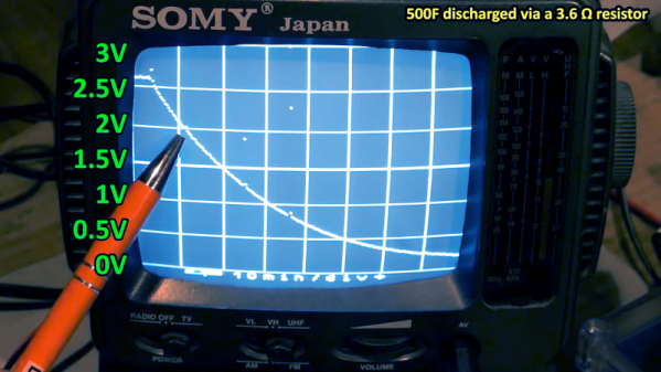
Supercapacitors use special techniques to achieve very high capacitance values. For example, the first unit in the video is a 500 F capacitor. That’s not a typo — not microfarads or even millifarads — a full 500 Farads. With reasonable resistance, it can take a long time to charge 500F, so it is easier to see the behavior, especially with the homemade scope, which probably won’t pick up very fast signals.

For example, A 350 mA charging current takes about an hour to bring the capacitor up to 2.6 V, just under its maximum rating of 2.7 V. Supercapacitors usually have low voltage tolerance. Their high capacity makes them ideal for low-current backup applications where you might not want a rechargeable battery because of weight, heat, or problems with long-term capacity loss.

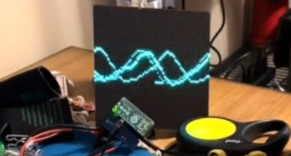
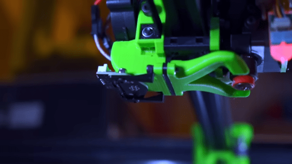
The real star of the video, though, is the cast of homemade test equipment, including the oscilloscope, a power supply, and a battery analyzer. To be fair, he also has some store-bought test gear, too, and the results seem to match well.

Supercapacitors are one of those things that you don’t need until you do. If you haven’t had a chance to play with them, check out the video or at least watch it to enjoy the homebrew gear. We usually look to [Andreas Spiess] for ESP32 advice, but he knows about supercaps, too. If you really like making as much as you can, you can make your own supercapacitors.

Continue reading “Homemade Scope Does Supercapacitor Experiments”

Russia’s New Mystery Shortwave Station

The Buzzer, also known as UVB-76 or UZB-76, has been a constant companion to anyone with a shortwave radio tuned to 4625 kHz. However, [Ringway Manchester] notes that there is now a second buzzer operating near in frequency to the original. Of course, like all mysterious stations, people try to track their origin. [Ringway] shows some older sites for the Buzzer and the current speculation on the current transmitter locations.

Of course, the real question is why? The buzzing isn’t quite nonstop. There are occasional voice messages. There are also jamming attempts, including one, apparently, by Pac Man.

Some people think the new buzzer is an image, but it doesn’t seem to be the same signal. The theory is that the buzzing is just to keep the frequency clear in case it is needed. However, we wonder if it isn’t something else. Compressed data would sound like noise.  Other theories are that the buzzing studies the ionosphere or that it is part of a doomsday system that would launch nuclear missiles. Given that the signal has broken down numerous times, this doesn’t seem likely.

What’s even stranger is that occasional background voices are audible on the signal. That implies that buzzing noise isn’t generated directly into the transmitter but is a device in front of a microphone.

We’ve speculated on the buzzer and the jamming efforts around it before. Not exactly a numbers station, but the same sort of appeal.

Continue reading “Russia’s New Mystery Shortwave Station”

Reactivating A Harris RF-130 URT-23 Transmitter

If you enjoy old military hardware, you probably know that Harris made quite a few heavy-duty pieces of radio gear. [K6YIC] picked up a nice example: the Harris RF-130 URT-23. These were frequently used in the Navy and some other service branches to communicate in a variety of modes on HF. The entire set included an exciter, an amplifier, an antenna tuner, and a power supply and, in its usual configuration, can output up to a kilowatt. The transmitter needs some work, and he’s done three videos on the transmitter already. He’s planning on several more, but there’s already a lot to see if you enjoy this older gear. You can see the first three below and you’ll probably want to watch them all, but if you want to jump right to the tear down, you can start with the second video.

You can find the Navy manual for the unit online, dated back to 1975. It’s hard to imagine how much things have changed in 50 years. These radios use light bulbs and weigh almost 500 pounds. [Daniel] had to get his shop wired for 220 V just to run the beast.

It is amusing that some of this old tube equipment had a counter to tell you how many hours the tubes inside had been operating so you could replace them before they were expected to fail. To keep things cool, there’s a very noisy 11,000 RPM fan. The two ceramic final amplifier tubes weigh over 1.5 pounds each!

The third video shows the initial power up. Like computers, if you remember when equipment was like this, today’s lightweight machines seem like toys. Of course, everything works better these days, so we won’t complain. But there’s something about having a big substantial piece of gear with all the requisite knobs, switches, meters, and everything else.

We can’t wait to see the rest of the restoration and to hear this noble radio on the air again. You can tell that [Daniel] loves this kind of gear and you can pick up a lot of tips and lingo watching the videos.

Continue reading “Reactivating A Harris RF-130 URT-23 Transmitter”

Photoplotting PCBs With A 3D Printer

Do you ever wonder why your PCB maker uses Gerber files? It doesn’t have to do with baby food. Gerber was the company that introduced photoplotting. Early machines used a xenon bulb to project shapes from an aperture to plot on a piece of film. You can then use that film for photolithography which has a lot of uses, including making printed circuit boards. [Wil Straver] decided to make his own photoplotter using a 3D printer in two dimensions and a UV LED. You can see the results in the video below.

A small 3D printed assembly holds a circuit board, the LED, and a magnet to hold it all to the 3D printer. Of course, an LED is a big large for a PCB trace, so he creates a 0.3 mm aperture by printing a mold and using it to cast epoxy to make the part that contacts the PCB film.

Continue reading “Photoplotting PCBs With A 3D Printer”

String Operations The Hard(ware) Way

One of the interesting features of the 8086 back in 1978 was the provision for “string” instructions. These took the form of prefixes that would repeat the next instruction a certain number of times. The next instruction was meant to be one of a few string instructions that operated on memory regions and updated pointers to the memory region with each repeated operation. [Ken Shirriff] examines the 8086 die up close and personal to explain how the 8086 microcode pulled this off and it is a great read, as usual.

In general, the string instructions wanted memory pointers in the SI and DI registers and a count in CX. The flags also have a direction bit that determines if the SI and DI registers will increase or decrease on each execution. The repeat prefix could also have conditions on it. In other words, a REP prefix will execute the following string instruction until CX is zero. The REPZ and REPNZ prefixes would do the same but also stop early if the zero flag was set (REPZ) or not set (REPNZ) after each operation. The instructions can work on 8-bit data or 16-bit data and oddly, as [Ken] points out — the microcode is the same either way.

[Ken] does a great job of explaining it all, so we won’t try to repeat it here. But it is more complicated than you’d initially expect. Partially this is because the instruction can be interrupted after any operation. Also, changing the SI and DI registers not only have to account for increment or decrement, but also needs to understand the byte or word size in play. Worse still, an unaligned word had to be broken up into two different accesses. A lot of logic to put in a relatively small amount of silicon.

Even if you never design a microcoded CPU, the discussion is fascinating, and the microphotography is fun to look at, too. We always enjoy [Ken’s] posts on little CPUs and big computers.

Building The OhSillyScope

If you have a Raspberry Pi connected to an LED matrix, you might think about creating a simple oscilloscope. Of course, the Pi isn’t really well-suited for that and neither is an LED matrix, so [Thomas McDonald] decided to create the OhSillyScope, instead.

The device isn’t very practical, but it does add some flash to live music performances or it makes a cool music visualizer. The matrix is only 64×64 so you can’t really expect it to match a proper scope. Besides that, it pulls its data from the Pi’s ALSA sound system.

You can find a video of the device on [Thomas’] Reddit post and a few additional videos on his Instagram account. Looks like a fun project and it also serves as a nice example if you need to read data from the sound card or drive that particular LED matrix.

We might have opted for PortAudio if we had written the same code, but only because it is more portable, which probably doesn’t matter here. Of course, you could also use GNURadio and some Python to drive the display. As usual, plenty of ways to solve any given problem.

Fast Scanning Bed Leveling

The bane of 3D printing is what people commonly call bed leveling. The name is a bit of a misnomer since you aren’t actually getting the bed level but making the bed and the print head parallel. Many modern printers probe the bed at different points using their own nozzle, a contact probe, or a non-contact probe and develop a model of where the bed is at various points. It then moves the head up and down to maintain a constant distance between the head and the bed, so you don’t have to fix any irregularities. [YGK3D] shows off the Beacon surface scanner, which is technically a non-contact probe, to do this, but it is very different from the normal inductive or capacitive probes, as you can see in the video below. Unfortunately, we didn’t get to see it print because [YGK3D] mounted it too low to get the nozzle down on the bed. However, it did scan the bed, and you can learn a lot about how the device works in the video. If you want to see one actually printing, watch the second, very purple video from [Dre Duvenage].

Generally, the issues with probes are making them repeatable, able to sense the bed, and the speed of probing all the points on the bed. If your bed is relatively flat, you might get away with probing only 3 points so you can understand how the bed is tilted. That won’t help you if your bed has bumps and valleys or even just twists in it. So most people will probe a grid of points.

Continue reading “Fast Scanning Bed Leveling”