Fritzing Is Back, And This Time It’s Written In JavaScript!

Fritzing has been stuck in the mud for just over a year now. There were no updates for many months, and members of the community wondered what was going on. Now, things might be turning around: Fritzing is being rebooted by community members, and there’s a roadmap of upcoming features.

The biggest takeaway from the GitHub discussion is that there simply aren’t enough developers for Fritzing. Fritzing is written in C++ and Qt, and there simply aren’t enough skilled devs to work on it. Future versions of Fritzing will be written in JavaScript.

Other developments in store for Fritzing include clearing out the number of open issues, making a new alpha, generally clean up the entire codebase, and prepare for a release. To that end, there’s also the Freetzing community to rebase the entire project with an emphasis on modularity.

Yes, Fritzing died a terrible death due to legal and funding issues. That still doesn’t mean Fritzing isn’t a valuable tool, though. With these new developments, and entirely new generation of hardware makers can dip their toes into the world of hardware development the easy way, and an entirely new generation of Open Source developers can work on making Fritzing the best tool it can be. There’s never been a better time to get started in Fritzing.

Create Green, Soldermasked PCBs With Fritzing

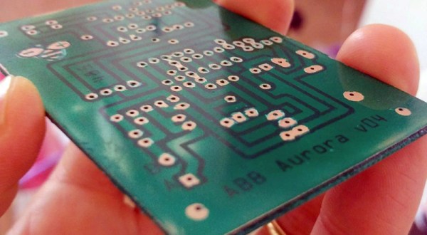
Even though you can easily order a PCB from any one of a dozen board houses and have it on your desk in a few weeks, there’s still a need for home-made circuit boards. If it’s because you have very special or strange requirements, you want to save money, or you need to suffer for your art, you can make printed circuit boards at home. You can even apply soldermask. It’s easy, and [Renzo] is here to show you how.

The beginnings of this tutorial cover well-tread territory such as building a CNC router, laying out a circuit, and cutting a piece of single-sided, copper clad board. If you stopped right there, after milling traces into a board, you would have a functioning circuit. But it wouldn’t look good; a piece of copper does not a PCB make, and you need soldermask. That’s where the real work comes in.

Applying the soldermask meant there needed to be places without soldermask, mostly the vias and through-holes. For this, [Renzo] pulled the copper pad layer out of Fritzing, printed it on a transparency sheet, and finally applied the UV-curing soldermask. This came as a kit, and right now, you can get 10 ml of green, red, blue, yellow, and black UV-curing soldermask, and a UV flashlight for ten dollars on the usual Internet shops. This soldermask was lathered on, rolled out, and exposed with the UV flashlight. After a quick wash in acetone, the result is a perfect PCB.

The Future Of Fritzing Is Murky At Best

Fritzing is a very nice Open Source design tool for PCBs, electrical sketches, and schematics for designers and artists to move from a prototype to real hardware. Over the years, we’ve seen fantastic projects built with Fritzing. Fritzing has been the subject of books, lectures, and educational courses, and the impact of Fritzing has been huge. Open up a book on electronics from O’Reilly, and you’ll probably see a schematic or drawing created in Fritzing.

However, and there’s always a however, Fritzing is in trouble. The project is giving every appearance of having died. You can’t register on the site, you can’t update parts, the official site lacks HTTPS, the Twitter account has been inactive for 1,200 days, there have been no blog posts for a year, and the last commit to GitHub was on March 13th. There are problems, but there is hope: [Patrick Franken], one of the developers of Fritzing and the president of the PCB firm Aisler which runs the Fritzing Fab, recently gave a talk at FOSDEM concerning the future of Fritzing. (That’s a direct FTP download, so have fun).

Continue reading “The Future Of Fritzing Is Murky At Best”

How To Design Custom Shaped Boards In Fritzing

If you’re looking to get started in designing a few PCBs, you could use one of the many software packages that allow you to create a PCB quickly, easily, and with a minimum amount of fuss. You could also use Fritzing.

Fritzing is terribad and you shouldn’t use it, but that doesn’t mean you still can’t abuse Fritzing to make it do what you want. [Arduino Enigma] recently posted a tutorial on how to design custom PCB shapes for Fritzing. Yes, Fritzing is no longer limited to rectangular PCBs with sharp corners. You can make PCBs in any shape with Fritzing, provided you spend a few hours futzing about with Inkscape.

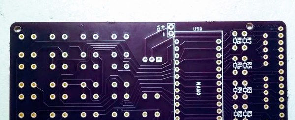
The goal for this project was to create a rectangular board without any sharp corners for [Arduino Enigma]’s Sinclair Scientific Calculator Emulator. Fritzing can make a board in the shape of a rectangle, in fact, that’s all it can do, but [Arduino Enigma] wanted a rectangle with radiused corners. After hours of work, we have the writeup on how to do it.

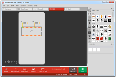
The imported board, with 3mm radiused corners.

The process to create a custom-shaped board, in this case, a rectangle with a 3mm radius on the corners, is simple. First, draw a rectangle of the desired shape, then draw even more rectangles as a sublayer of the current layer. Fritzing requires the layer ID to be named ‘board’, ‘silkscreen’ and ‘silkscreen0’, but this cannot be changed in Inkscape itself — you’ll need to edit the file with a text editor. After creating three layers, each containing the shape you want, simply trim the size of the page to the size of the board. Save the file, edit the file in a text editor, and click save. Launch Fritzing, load an image file, and select the SVG you’ve been working on. In just twenty or thirty quick steps, you too can import any shape you can imagine into Fritzing.

There is one pain point to this process. Editing the layer name manually with a text editor pushes this Fritzing hack from a baroque workaround into something that makes us all question the state of Open Source standards. Unfortunately, this is required because Inkscape does not use layer names as the ID in an SVG file. No, it doesn’t make sense, but that’s just the way it is.

For any other PCB design tool, creating a custom-shaped board is simply a matter of drawing a few lines. Fritzing is different, though. The top copper layer is represented as orange, and the bottom copper layer is yellow, a UI decision that doesn’t make sense, even if you aren’t colorblind. Putting more than two layers of copper on a Fritzing board is impossible. Fritzing is a tool you should avoid for PCB layout. That said, [Arduino Enigma] figured out how to do something in Fritzing that you’re not supposed to be able to do and that’s pretty cool.

Making An Arduino Shield PCB With Fritzing

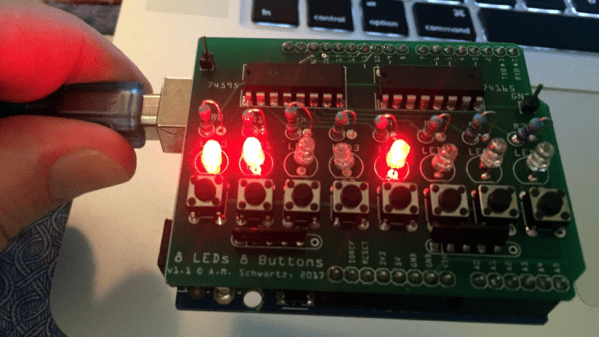
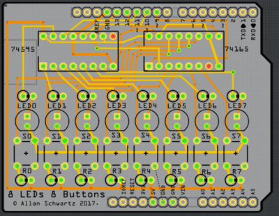
[Allan Schwartz] decided to document his experience using Fritzing to design, fabricate, and test a custom Arduino shield PCB, and his step-by-step documentation makes the workflow very clear. Anyone who is curious or has been looking for an opportunity to get started will find [Allan]’s process useful to follow. The PCB in question has two shift registers, eight LEDs, eight buttons, and fits onto an Arduino; it’s just complex enough to demonstrate useful design features and methods while remaining accessible.

[Allan] starts with a basic breadboard design, draws a schematic, prototypes the circuit, then designs the PCB and orders it online, followed by assembly and testing. [Allan] had previously taught himself to use Eagle and etched his own PCBs via the toner transfer method, but decided to use Fritzing instead this time around and found it helpful and easy to use.

About a year ago we saw Fritzing put through its paces for PCB design, and at the time found that it didn’t impress much from an engineering perspective. Regardless, as a hobbyist [Allan] found real value in using Fritzing for his project from beginning to end; he documented both the process and his observations in order to help others, and that’s wonderful.

Creating A PCB In Everything: Creating A Custom Part In Fritzing

This is the continuation of a series of posts where I create a schematic and PCB in various EDA tools. Already, we’ve looked at Eagle CAD, KiCad, and took a walk down memory lane with one of the first PCB design tools for the IBM PC with Protel Autotrax. One of the more controversial of these tutorials was my post on Fritzing. Fritzing is a terrible tool that you should not use, but before I get to that, I need to back up and explain what this series of posts is all about.

The introduction to this series of posts laid it out pretty bare. For each post in this series, I will take a reference schematic for a small, USB-enabled ATtiny85 development board. I recreate the schematic, recreate the board, and build a new symbol and footprint in each piece of software. That last part — making a new symbol and footprint — is a point of contention for Fritzing users. You cannot create a completely new part in Fritzing. That’s a quote straight from the devs. For a PCB design tool, it’s a baffling decision, and I don’t know if I can call Fritzing a PCB design tool now.

Continue reading “Creating A PCB In Everything: Creating A Custom Part In Fritzing”

Creating A PCB In Everything: Friends Don’t Let Friends Use Fritzing

This week, we’re continuing our Creating A PCB In Everything series, where we go through the steps to create a simple, barebones PCB in different EDA suites. We’re done with Eagle, and now it’s time to move onto Fritzing.

fritzing-logoFritzing came out of the Interaction Design Lab at the University of Applied Sciences of Potsdam in 2007 as a project initiated by Professor Reto Wettach, André Knörig and Zach Eveland. It is frequently compared to Processing, Wiring, or Arduino in that it provides an easy way for artists, creatives, or ‘makers’ to dip their toes into the waters of PCB design.

I feel it is necessary to contextualize Fritzing in the space of ‘maker movement’, DIY electronics, and the last decade of Hackaday. Simply by virtue of being an editor for Hackaday, I have seen thousands of homebrew PCBs, and tens of thousands of amateur and hobbyist electronics projects. Despite what the Fritzing’s Wikipedia talk page claims, Fritzing is an important piece of software. The story of the ‘maker movement’ – however ill-defined that phrase is – cannot be told without mentioning Fritzing. It was the inspiration for CircuitLab, and the Fritzing influence can easily be seen in Autodesk’s 123D Circuits.

Just because a piece of software is important doesn’t mean it’s good. I am, perhaps, the world’s leading expert at assessing poorly designed and just plain shitty PCBs. You may scoff at this, but think about it: simply due to my vocation, I look at a lot of PCBs made by amateurs. EE professors, TAs, or Chris Gammell might beat me on volume, but they’re only looking at boards made by students using one tool. I see amateur boards built in every tool, and without exception, the worst are always designed in Fritzing. It should be unacceptable that I can even tell they’re designed in Fritzing.

Fritzing has its place, and that place is building graphical representations for breadboard circuits. Fritzing has no other equal in this respect, and for this purpose, it’s an excellent tool. You can also make a PCB in Fritzing, and here things aren’t as great. I want to do Fritzing for this Creating A PCB In Everything series only to demonstrate how bad PCB design can be.

For the next few thousand words, I am going to combine a tutorial for Fritzing with a review of Fritzing. Fritzing is an important piece of software, if only for being a great way to create graphics of breadboard circuits. As a PCB design tool, it’s lacking; creating parts from scratch is far too hard, and there’s no way to get around the grid snap tool. No one should ever be forced to create a PCB in Fritzing, but it does have its own very limited place.

Continue reading “Creating A PCB In Everything: Friends Don’t Let Friends Use Fritzing”