How To Design Custom Shaped Boards In Fritzing

If you’re looking to get started in designing a few PCBs, you could use one of the many software packages that allow you to create a PCB quickly, easily, and with a minimum amount of fuss. You could also use Fritzing.

Fritzing is terribad and you shouldn’t use it, but that doesn’t mean you still can’t abuse Fritzing to make it do what you want. [Arduino Enigma] recently posted a tutorial on how to design custom PCB shapes for Fritzing. Yes, Fritzing is no longer limited to rectangular PCBs with sharp corners. You can make PCBs in any shape with Fritzing, provided you spend a few hours futzing about with Inkscape.

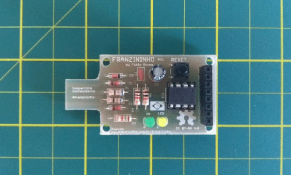
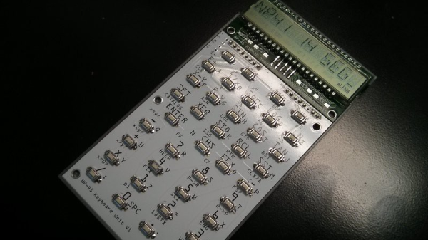
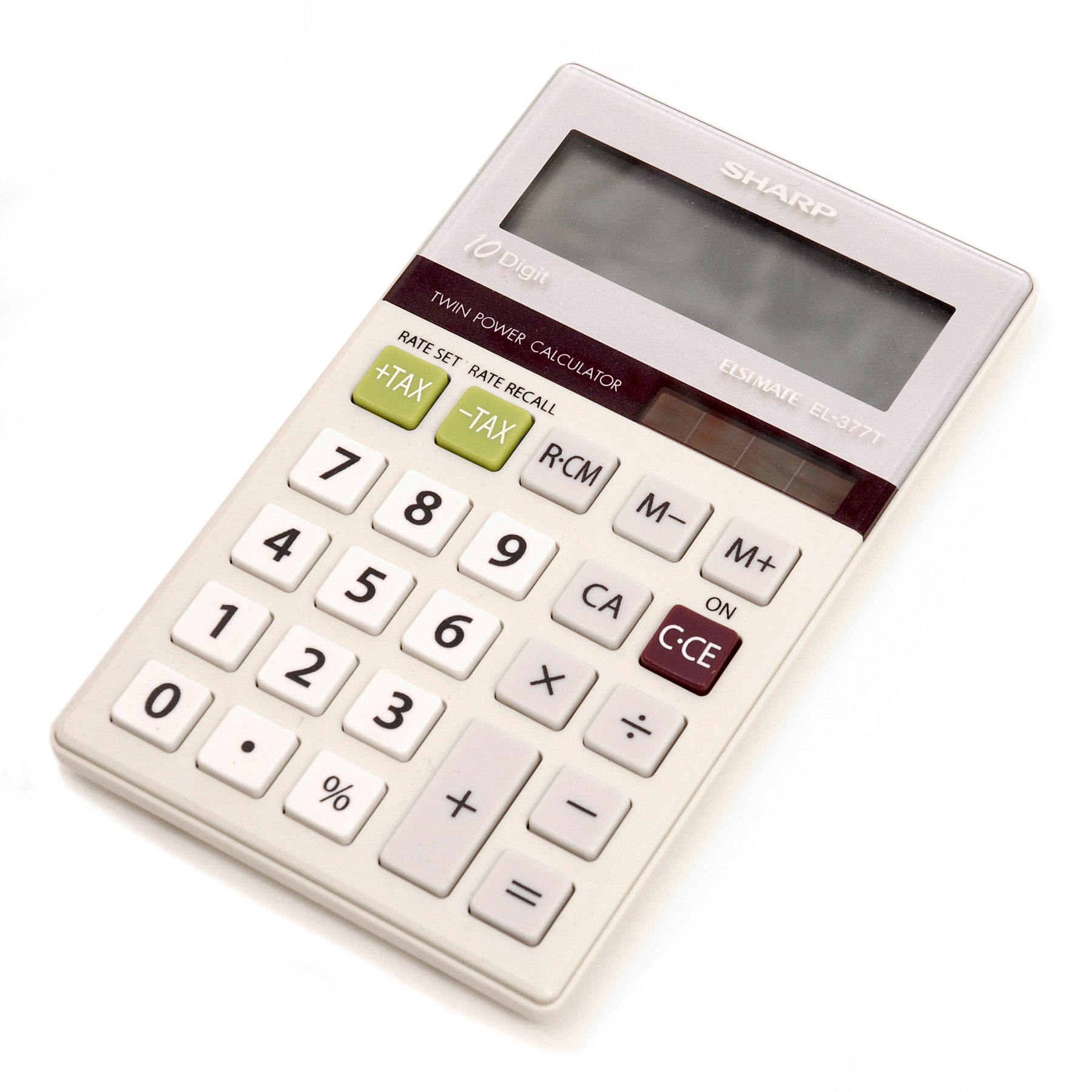
The goal for this project was to create a rectangular board without any sharp corners for [Arduino Enigma]’s Sinclair Scientific Calculator Emulator. Fritzing can make a board in the shape of a rectangle, in fact, that’s all it can do, but [Arduino Enigma] wanted a rectangle with radiused corners. After hours of work, we have the writeup on how to do it.

The imported board, with 3mm radiused corners.

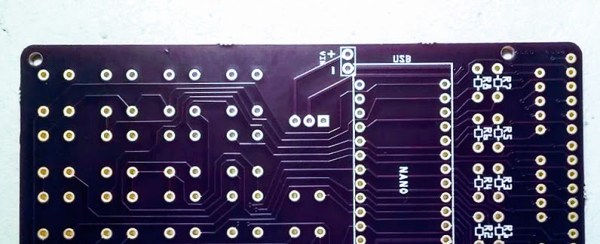
The process to create a custom-shaped board, in this case, a rectangle with a 3mm radius on the corners, is simple. First, draw a rectangle of the desired shape, then draw even more rectangles as a sublayer of the current layer. Fritzing requires the layer ID to be named ‘board’, ‘silkscreen’ and ‘silkscreen0’, but this cannot be changed in Inkscape itself — you’ll need to edit the file with a text editor. After creating three layers, each containing the shape you want, simply trim the size of the page to the size of the board. Save the file, edit the file in a text editor, and click save. Launch Fritzing, load an image file, and select the SVG you’ve been working on. In just twenty or thirty quick steps, you too can import any shape you can imagine into Fritzing.

There is one pain point to this process. Editing the layer name manually with a text editor pushes this Fritzing hack from a baroque workaround into something that makes us all question the state of Open Source standards. Unfortunately, this is required because Inkscape does not use layer names as the ID in an SVG file. No, it doesn’t make sense, but that’s just the way it is.

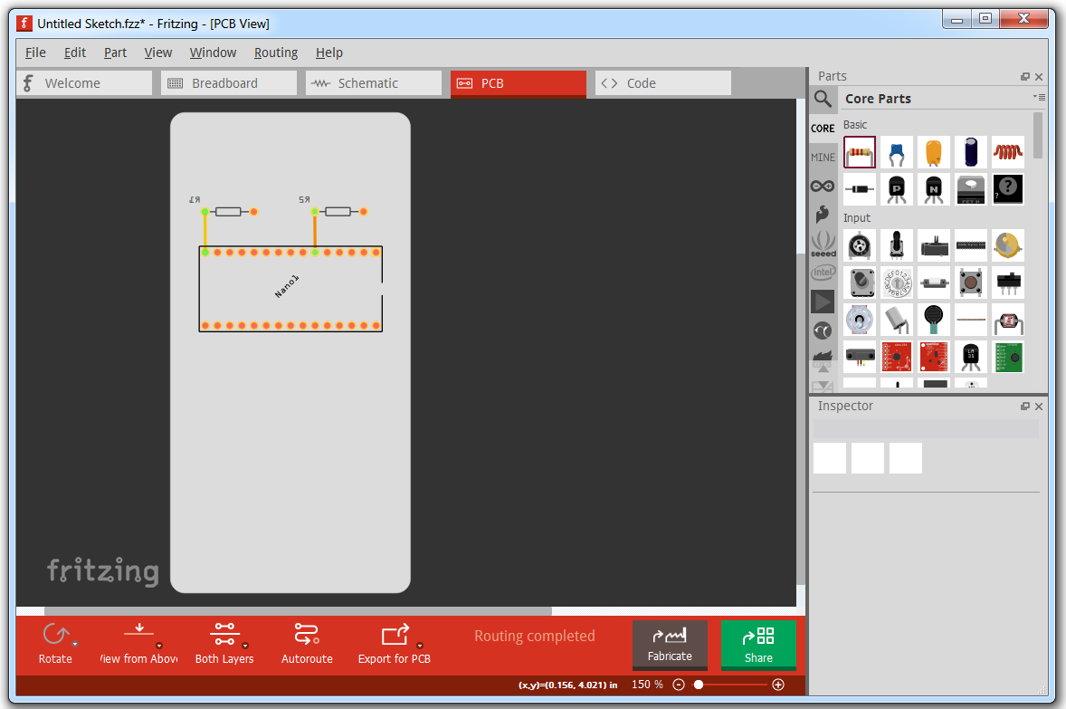
For any other PCB design tool, creating a custom-shaped board is simply a matter of drawing a few lines. Fritzing is different, though. The top copper layer is represented as orange, and the bottom copper layer is yellow, a UI decision that doesn’t make sense, even if you aren’t colorblind. Putting more than two layers of copper on a Fritzing board is impossible. Fritzing is a tool you should avoid for PCB layout. That said, [Arduino Enigma] figured out how to do something in Fritzing that you’re not supposed to be able to do and that’s pretty cool.

The Smaller, Tinier Arduino Platform

While many of the Arduino platforms are great tools for gaining easy access to microcontrollers, there are a few downsides. Price and availability may be the highest on the list, and for those reasons, some have chosen to deploy their own open-source Arduino-compatible boards.

The latest we’ve seen is the Franzininho, an Arduino Gemma-like board that’s based on the ATtiny85, a capable but tiny microcontroller by Atmel in a compact 8-pin configuration. This board has everything the Gemma has, including a built-in LED and breakout pins. One of the other perks of the Franzininho over the Gemma is that everything is based on through-hole components, making the assembly much easier than the surface mount components of the Gemma.

It’s worth noting that while these boards are open source, the Arduinos are as well. It’s equally possible to build your own 100% identical Arduino almost as easily. If you want more features, you can add your own by starting from one of these platforms and do whatever you want with it, like this semi-educational Atmel breakout board.

Thanks to [Clovis] for the tip!

Build Your Own Rowing Machine, Now With Digital Readout!

An ergometer is a fancy fitness word for a rowing machine, a device which can be used to work out the muscles used in rowing. It’s an excellent cardio workout that can also build upper body strength, and resistance can be varied depending on the individual’s fitness goals. But perhaps you need to measure your workout to see your progress – in which case, [Dave]’s instrumentation package might be right up your alley.

The basic mechanical build involves a wooden frame, fitted with a rowing setup built around a modified bicycle wheel. The wheel has vanes attached, made of what appears to be cut sections of PVC pipe. These act essentially as dampers, using the air to create the resistance for the rower to work against.

The wheel is instrumented with a chopper wheel and an IR optical switch, which measures the rotational speed of the wheel during rowing. This signal is fed into an ATMega328 which runs the calculations on the rower’s performance. It’s all fed to a Nokia 5110 screen for display, which makes a lovely throwback for those that remember the brick fondly.

[Dave] touches not only on the electronic aspects of the build, but also does an excellent job of breaking down the mathematics behind rowing performance. It’s a great resource that builds on top of the excellent work by the OpenErgo project.

If we’ve whet your thirst for exercise machine hacks, you’d better check out this treadmill to belt grinder mod.

Spraychalk Anoints Your Sidewalks With Precision Sandprints

Giant lines in the sand are incredibly useful for pleasing the gods and hailing overpassing extraterrestrials. Beautiful, unwarranted spray-painted sidewalks might land you in detention with local law enforcement. Of course, why not have both? With the Sand-and-Spraychalk machine, you can!

The Sand-and-Spraychalk machine Is a moving two-axis CNC machine that can anoint its path with a spray of either sand bits or spray paint.  As with any self-respecting power tool these days, the Spraychalk is driven by a rechargeable Bosch 18 V battery pack. As far as safety goes, leveraging an already-product-proven solution instead of cooking our lawns with questionable LiPos is downright clever.

Elegance is in simplicity, and the Spraychalk is no exception. The entire build is a collection of off-the-shelf parts mixed with a few laser cut plates and a one custom nozzle made of POM (Acetal). Precise spraying might sound like a hard problem, but it’s executed here with just a motor-driven cam and a couple levers. Finally, adapting a 18 V battery pack may seem like a form-factor nightmare, but our creator, [kallibaba], managed to pull it off with just a few laser-cut plates.

The Spraychalk rightfully sits next to its previously mentioned cousins that have graced these pages before. The next time we’re wondering just who vandalized your lawn so majestically, we know where to look!

Continue reading “Spraychalk Anoints Your Sidewalks With Precision Sandprints”

Nonpareil RPN HP-41 Calculator Build

The early HP Reverse Polish Notation calculators have a special place in the hearts of engineers and tinkerers as there are lots of projects involving them. They haven’t been produced in decades, but [Chris Chung] has used some open source code to create DIY hardware version of the HP-41 Reverse Polish Notation (RPN) calculator.

The open source code behind the calculator is the Nonpareil High-Fidelity Calculator Simulator, and [Chris] has used it along with a custom designed readout and PCBs to create a working prototype. The simulator uses the original byte code of the HP-41 so the its behavior is exactly the same as the original calculator.

[Chris] has designed the PCBs so that the buttons and the screen are separate and join together. This neat idea means that he can try out different screens or different button PCBs and mix-and-match to find the combination that works best. He’s also designed a 3D printed case for the calculator. He does prefer using the bare buttons on the board to the 3D printed ones he printed for use with the case.

We love calculators here so there have been a bunch of articles over the years. Check out the documentation that comes along with this open source calculator, or check out this pocket calculator that emulates two other pocket calculators!

Continue reading “Nonpareil RPN HP-41 Calculator Build”

Calculus And A Calculator

Earlier this year, [Dan Maloney] went inside mechanical calculators. Being the practical sort, [Dan] jumped right into the Pascaline invented by Blaise Pascal. It couldn’t multiply or divide. He then went into the arithmometer, which is arguably the first commercially successful mechanical calculator with four functions. That was around 1821 or so. But [Dan] mentions it used a Leibniz wheel. I thought, “Leibniz? He’s the calculus guy, right? He died in 1716.” So I knew there had to be at least a century of backstory to get to the arithmometer. Having a rainy day ahead, I decided to find out exactly where the Leibniz wheel came from and what it was doing for 100 years prior to 1821.

If you’ve taken calculus you’ve probably heard of Gottfried Wilhelm Leibniz (who would have been 372 years old on July 1st, by the way). He’s the guy that gave us the notation we use in modern calculus and oddly was one of two people who apparently figured out calculus, the other being Issac Newton. Both men, by the way, accused each other of stealing, although it is more likely they both built on the same prior work. When you are struggling to learn calculus, it is sometimes amazing that not only did someone think it up, but two people thought it up at one time. However, Leibniz also built what might be the first four function calculator in 1694. His “stepped reckoner” used a drum and some cranks and the underlying mechanism found inside of it lived on until the 1970s in other mechanical calculating devices. Oddly, Leibniz didn’t use the term stepped reckoner but called the machine Instrumentum Arithmeticum.

Many of us remember when a four function electronic calculator was a marvel and not even very inexpensive. Nowadays, you’d have to look hard to find one that only had four functions and simple calculators are cheap enough to give away like ink pens. But in 1694, you didn’t have electronics and integrated circuits necessary to pull that off.

Continue reading “Calculus And A Calculator”

Friday Hack Chat: Fire And Cars

Summer is here, and it’s time for the question on everyone’s mind: how are they going to get the fuselage of a 747 from the California desert to Burning Man? You can’t put it on a train, and it’s much wider than any truck.

This Friday, we’re not going to be answering the modern-day riddle of the Sphinx, but we are going to the talking about other art cars. For this week’s Hack Chat, we’re going to be discussing dragons made out of school buses and pyrotechnics.

Our guest for this Hack Chat will be [Kevin Bracken], best known as the founder of International Pillow Fight Day, but now he’s the project lead fo Heavy Meta, Canada’s largest art car and fire-breathing dragon sculpture/stage. Heavy Meta is a 30-foot long mutant vehicle with flame effects and a 15,000 watt sound system. It’s also the 3tress, a 2,000 square foot workshop founded with the purpose of building this gigantic art car, and it’s the Toronto Art Car Community, a group of people tasked with manufacturing gigantic lumbering behemoths.

Kevin will be discussing how the Heavy Meta crew transformed a GMC school bus into a dragon, how the team learned to build flame effects, how the pneumatics work, and what it’s like to be on tour with half a dozen Maker Faires.

During this Hack Chat, we’ll be talking about:

  • What an art car is
  • How do you make the electronics
  • What precautions do you take to keep it working on the road
  • How do you control flame effects
  • What are the legal and regulatory considerations of art cars

You are, of course, encouraged to add your own questions to the discussion. You can do that by leaving a comment on the Hack Chat Event Page and we’ll put that in the queue for the Hack Chat discussion.join-hack-chat

Our Hack Chats are live community events on the Hackaday.io Hack Chat group messaging. This week is just like any other, and we’ll be gathering ’round our video terminals at noon, Pacific, on Friday, July 6th.  Here’s a clock counting down the time until the Hack Chat starts.

Click that speech bubble to the right, and you’ll be taken directly to the Hack Chat group on Hackaday.io.

You don’t have to wait until Friday; join whenever you want and you can see what the community is talking about.