What’s not to love about animatronics? Just peel back any puppet’s silicone skin to uncover a cluster of mechatronic wizardry that gives it a life on the big screen. I’ve been hunting online for a good intro to these beasts, but I’ve only turned up one detailed resource–albeit a pretty good one–from the Stan Winston Tutorials series. Only 30 seconds into the intro video, I could feel those tentacles waking up my lowest and most gutteral urge to create physical things. Like it or not, I was hooked; I just had to build one… or a few. This is how you built a very real animatronic tentacle.

If you’re getting started in this realm, I’ll be honest: the Stan Winston Tutorial is actually a great place to start. In about two hours, instructor Richard Landon covers the mindset, the set of go-to components, and the techniques for fabricating a tentacle mechanism with a set of garage tools–not to mention giving us tons of real-film examples along the way [1].
We also get a sneak peek into how we might build more complicated devices from the same basic techniques. I’d like to pick up exactly where he left off: 4-way two-stage tentacles. And, of course, if you’ve picked up on just how much I like a certain laser-cuttable plastic at this point, I’m going to put a modern twist on Landon’s design. These design tweaks should enable you to build your own tentacle and controller with nothing more but a few off-the-shelf parts, some Delrin, and a laser cutter… Ok, fine, a couple 3D printed parts managed to creep their way in too.
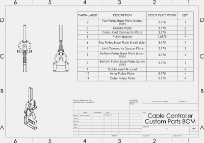 In a good-ol’ engineers-for-engineers fashion, I’m doing something a little different for this post: I’m finishing off this series with a set of assembly videos, a BOM, and the original CAD files to make that beast on the front page come to life. As for why, I figured: why not? Even though these mechanisms have lived in the robotics community and film industry for years, they’re still lacking the treatment of a solid, open design. This is my first shot at closing that gap. Get yourself a cup of coffee. I’m about to give you every bleeding detail on the-how-and-why behind these beasts.
All right; let’s get started.
Continue reading “The Bootup Guide To Homebrew Two-Stage Tentacle Mechanisms”