Extremely Detailed FMCW Radar Build

A lot of hackers take the “learn by doing” approach: take something apart, figure out how it works, and re-purpose all of the parts. [Henrik], however, has taken the opposite approach. After “some” RF design courses, he decided that he had learned enough to build his own frequency-modulated continuous wave radar system. From the level of detail on this project, we’d say that he’s learned an incredible amount.

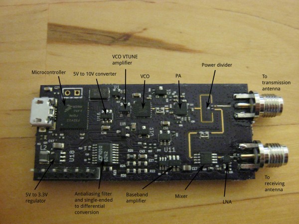
[Henrik] was looking to keep costs down and chose to run his radar in the 6 GHz neighborhood. This puts it right in a frequency spectrum (at least in his area) where radar and WiFi overlap each other. This means cheap and readily available parts (antennas etc) and a legal spectrum in which to operate them. His design also includes frequency modulation, which means that it will be able to determine an object’s distance as well as its speed.

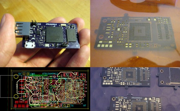
There are many other design considerations for a radar system that don’t enter into a normal project. For example, the PCB must have precisely controlled trace widths so that the impedance will exactly match the design. In a DC or low-frequency AC system this isn’t as important as it is in a high-frequency system like this. There is a fascinating amount of information about this impressive project on [Henrik]’s project page if you’re looking to learn a little more about radio or radar.

Too daunting for you? Check out this post on how to take on your first radar project.

An Amazing DIY Single Board ARM Computer With BGA

DIY Single Board Computer ARM

Typically, you buy a single board Linux computer. [Henrik] had a better idea, build his own ARM based single board computer! How did he do it? By not being scared of ball grid array (BGA) ARM processors.

Everyone loves the Raspberry Pi and Beagle Board, but what is the fun in buying something that you can build? We have a hunch that most of our readers stay clear of BGA chips, and for good reason. Arguably, one of the most important aspects of [Henrik’s] post is that you can easily solder BGAs with cheaply available tools. OSH Park provides the inexpensive high-quality PCBs, OSH Stencils provides the inexpensive stencils, and any toaster oven allows you to solder even the most difficult of components. Not only does he go over the PCB build, he also discusses the bootloader, u-boot, and how to get Linux running.

Everything worked out very well for [Henrik]. It’s a good thing too, cause we sure wouldn’t want to debug a PCB as complicated as this one. What projects have you built that use a BGA? Let us know how it went!

Geiger Counter Tells You If Your Dishes Are Radioactive

geiger-counter-build

[Henrik] really turned out a nice little Geiger counter board based on a cold war era Geiger tube.

It works in much the same way as other projects along the same lines. It does run on batteries if needed, which is no small feat since the tube wants high voltage to operate correctly. And the video after the break shows it spitting out readings to a terminal window when connected to a computer via USB.

But what really caught our eye is the radioactive source material he used for testing. Since he didn’t have anything on hand he had to order something, and ended up going with a couple shards from a dinner plate. A radioactive dinner plate to exact and it’s a brand name you’ve probably heard of before. Red Fiesta Ware apparently used to be radioactive. It’s even mentioned in the intro to the Wikipedia article. Go figure!

One other thing we noticed was [Henrik’s] method of interfacing his multimeter with a breadboard. One of the project photos shows the probe with thin wire wrapped around the tip. We assume this is to make it easy to plug into the breadboard.

Despite this little digression away from the main project we did really enjoy learning about his build. And you can see him showing it off in the clip after the break.

Continue reading “Geiger Counter Tells You If Your Dishes Are Radioactive”

On Not Designing Circuits With Evolutionary Algorithms

[Henrik] has been working on a program to design electronic circuits using evolutionary algorithms. It’s still very much a work in progress, but he’s gotten to the point of generating a decent BJT inverter after 78 generations (9 minutes of compute time), as shown in the .gif above.

To evolve these circuits, [Henrik] told a SPICE simulation to generate an inverter with a 5V power supply, 2N3904 and 2N3906 transistors, and whatever resistors were needed. The first dozen or so generations didn’t actually do anything, but after 2000 generations the algorithm produced a circuit nearly identical to the description of a CMOS inverter you’d find in a circuit textbook.

Using evolution to guide electronic design is nothing new; an evolutionary algorithm and a a few bits of Verilog can turn an FPGA into a chip that can tell the difference between a 1kHz and 10kHz tone with extremely minimal hardware requirements. There’s also some very, very strange stuff that happened in this experiment; the evolutionary algorithm utilized things that are impossible for a human to program and relies on magnetic flux and quantum weirdness inside the FPGA.

[Henrik] says his algorithm didn’t test for how much current goes through the transistors, so implementing this circuit outside of a simulation will destroy the transistors and emit a puff of blue smoke. If you’d like design your own circuits using evolution, [Henrik] put all the code in a git for your perusal. It’s damn cool as it stands now, and once [Henrik] includes checking current and voltage in each component his project may actually be useful.