Simple USB Power Meter

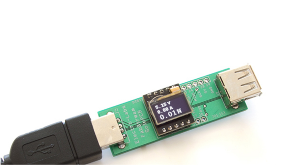
The USB interface is being increasingly used as a power supply and charging port for all kinds of devices, besides data transfer. A meter to measure the electrical parameters of devices connected to a USB socket or charger would be handy on any hacker workbench. The folks at [electro-labs] designed this simple USB power meter which does just that.

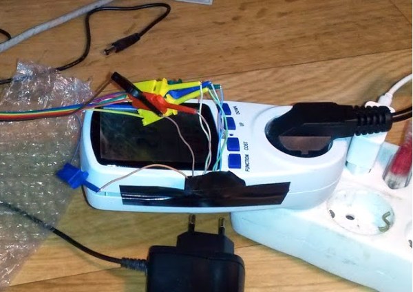
The device measures voltage and current and displays them, along with the calculated power, on the small 0.5″ OLED display. The circuit is built around an ATmega328. To keep the board size small, and reduce component count, the microcontroller is run off its internal 8MHz clock. A low-resistance shunt provides current sensing which is amplified by the LT6106 a high side current sense amplifier before being fed to the 10 bit analog port of the ATmega. A MCP1525 precision voltage reference provides 2.5V to the Analog reference pin of the microcontroller, resulting in a 2.44mV resolution. Voltage measurement is via a resistive divider that has a range of up to 6V. An Arduino sketch reads voltage and current data on the analog ports and displays measurements on the display. The measured data is averaged to filter out noise.

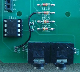
The OLED display has a SPI interface and requires the u8glib library. The project uses all SMD parts, but is fairly easy to assemble by hand and could be a nice starter project if you want to wet your feet on surface mount assembly techniques. It’s designed using SolaPCB EDA software, and the source files for schematic and board layout are available as a ZIP archive. Download the BoM and Arduino code and you have everything needed to build this nifty device.

Thanks to [Abdulgafur] for sending in this tip. And if you are looking for a more comprehensive solution, check the awesome Friedcircuits USB Tester which we reviewed earlier and is available in the Hackaday Store.

Self Built Power Meter Uses Dual Sense Transformers

[Renaud] built a AC power meter from scratch. While commercial power meters like the Kill A Watt are available [Renaud’s] build gives an interesting insight into the methods used.

currentAt the heart of [Renaud’s] design lie two sense transformers. The first is a typical voltage stepdown transformer. This brings the AC line voltage down to +/- 10V, which is more amenable to digital sampling. The second is a current sense transformer. In current transformers the primary is typically a single wire (the AC line in this case) passing through the middle of a ring (see the picture to the right from wikipedia). The secondary is wrapped round the ring. When the secondary coil is shorted a current in the primary wire/coil induces a current in the secondary coil.

In practice, the voltage drop across a low value resistor is used to detect the current in the secondary. Clamp meters use this principle to make non-contact current measurements. Other power meters often use hall effect sensors for current measurements. It will be interesting to see how these methods compare when [Renaud] benchmarks this build.

[Renaud] takes the voltage and current readings from these transformers and samples them with a PIC in order to calculate power. As the AC voltage is periodic [Renaud] uses a method similar to Equivalent Time Sampling (ETS) to combine waveforms from multiple cycles and increase the effective sample rate.

Great stuff [Renaud]!

Cheap Power Meter

Digital Data From A Cheap Power Meter

Power meters like the Kill-A-Watt are great for keeping track of energy usage, and are also very hackable. The Kill-a-Watt in particular puts out analog signals proportional to current and voltage, which makes it easy to interface with a microcontroller.

Although reading analog voltages is easy enough, [Kalle] found a cheap Chinese power meter that is even more hackable. These inexpensive power meters cost about the same as a first-generation Kill-a-Watt, but they directly stream out digital data. The power meter [Kalle] hacked has a non-US plug, but the meter is available from the usual suppliers (eBay, Aliexpress, etc) with a 3-prong US plug and 120v rating.

After breaking out a logic analyzer, [Kalle] discovered that the meter constantly streams voltage, current, and power data from the measurement board to the display board on a SPI-like bus. The ribbon cable inside the meter even has the clock and data bus lines clearly labelled. [Kalle] went on to reverse-engineer the protocol and write an Arduino sketch that parses the stream, making it even easier to integrate this meter into your next power monitoring project.

A WiFi Home Power Meter

acFor his masters at Cornell, [Christopher McNally] designed a simple, non intrusive home power meter capable of doing everything a ‘smart meter’ can do – log power consumption throughout a home, and display a log of a home’s power consumption over WiFi. He’s even testing out some interesting ideas, like automatically detecting when specific devices turn on by reading the current data.

From [Chris]'[Jeramy] developed his system around the Arduino and a Ethernet shield, taking care of networking and choosing a micro, leaving him more time to develop the more interesting part of the project: sensing current. For this he used a small, clip-on current transducer. This sensor generates up to 10 VAC across a resistor, but the Arduino doesn’t play well with AC, requiring a small rectifier built around an op amp.

While the project works as a homebrew smart meter, [Jeramy] wasn’t able to automatically detect when certain devices were powered on. This is partly due to the fact that changes in current were only seen in magnitude and not waveform. Also, if two devices were powered on at the same time, the software would see that as a larger device that draws the sum of the current of two smaller devices. Still, [Jeramy] came up with a cheap way of metering power in any home, and the cost of his solution is cheaper than a lot of professional systems out there.

All the code, files, and design report are available on [Jeramy]’ git.

Build And Install Your Own High-end Cycling Power Meter

Cycling power meters can set you back quite a pretty penny. [Keith] quotes prices starting at $1500 and going up to $4000. We know several serious cyclists who would think twice about spending that on a bike, and wouldn’t even consider putting that kind of investment into an accessory for it. But if you’ve got the time [Keith] will show you how to build and install your own cycling power meter.

The link above is a roundup of all the posts and videos [Keith] made along the way. We’ve embedded his introduction video after the break where he discusses the goals of the project. The system allows for independently measuring the power of each leg. This is accomplished using strain gauges on the cranks to monitor torque. This data is combined with cadence measurements (how fast the rider is turning the cranks) which is all that is necessary to calculate the power output of the rider.

The parts list comes in at about $350. This doesn’t include the equipment he used to test and calibrate his calculations.

Continue reading “Build And Install Your Own High-end Cycling Power Meter”

OCR Automatically Reads A Power Meter

ocr-used-to-read-a-power-meter

[Chris] tried his hand at using Optical Character Recognition in his server power monitoring rig. The image above is what the IP camera used in the setup sees. He’s included a bright light to ensure that the contrast is as great as possible. After applying a threshold filter to the captured still, he is able to process the image to test all seven segments of every digit.

He uses Mathematica for the processing. We’re not familiar with the particulars of the language, but it’s easy enough to see the main parts of the program. Line six of his source code applies the image filters and then the program loops through the assigned location of each digit, testing segment combinations to ascertain what number is shown. Things get hairy when it comes to the decimal point. We gather that the meter can show varying degrees of precision based on the total number of digits needed (like a Digital Multimeter). But [Chris’] setup has a difficult time reliably detecting that decimal point because of its size. He uses a shortcut to get around this, knowing that his server never pulls less than 300W so he corrects the output (by multiplying it by ten) if the reading is below that benchmark.

Of course it would be easier to crack open the monitor and glean data electronically (that’s how the Tweet-A-Watt does it) but then [Chris] wouldn’t have had the fun of playing with OCR.

Another Approach To Power Meter Data Harvesting

[Dodgy] wrote in to talk about his power meter data harvesting programs. This uses the same hardware by CurrentCost as the hack we looked at over the weekend but [Dodgy’s] implementation is different. It’s separated into two parts, the first is a webserver written in C that harvests the data and makes it available at an address on the network, the second is written in Perl to format and upload data to Google PowerMeter.

The C program serves data on a configurable port, defaulting to 3090. All of the data can be accessed in one line of code by loading http://127.0.0.1:3090, or individually with subdirectories like /watts, /time, or /tempr. From there you can do what you want with the data. The second part of [Dodgy’s] suite is a Perl script that polls the C server and sends the data to your Google account.

One thing that interests us is his comment that you should be able to compile the server side C code for an embedded device. It would be a nice energy savings to be able to upload data regularly without a PC running constantly.