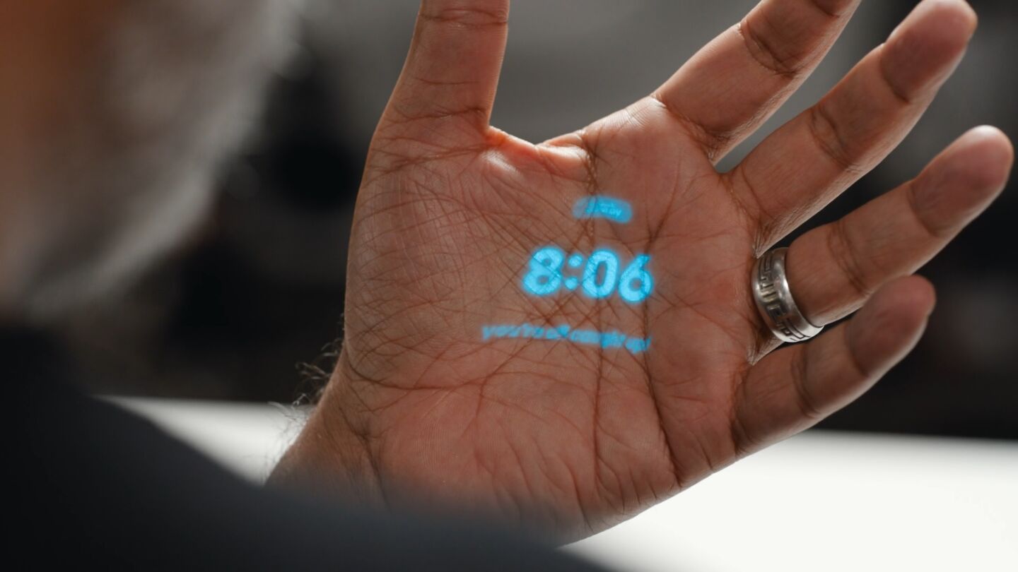
The Pi Pico, An SDR Receiver Front End

Making a software defined radio (SDR) receiver is a relatively straightforward process, given the right radio front end electronics and analogue-to-digital converters. Two separate data streams are generated using clocks at a 90 degree phase shift, and these are passed to the software signal processing for demodulation. But what happens if you lack a pair of radio front ends and a suitable clock generator? Along comes [Mordae] with an SDR using only the hardware on a Raspberry Pi Pico. The result is a fascinating piece of lateral thinking, extracting something from the hardware that it was never designed to do.

The onboard RP2040 ADC is of course far too slow for the task, so instead an input is used, with a negative feedback arrangement from another GPIO to form a crude 1-bit ADC. A PIO peripheral is then used to perform the quadrature mixing, resulting in the requisite pair of data streams. At this point these are sent over USB to GNU Radio for demodulating, mainly for convenience rather than necessarily because the microcontroller lacks the power.

The result is a working SDR front end, demonstrated pulling in an FM broadcast station. The Pico has to be overclocked to reach that frequency and it’s more than a little noisy, but we’re extremely impressed with how much has been done with so little. Oddly it isn’t the first Pico SDR we’ve seen, but the previous one was a much more conventional and lower-frequency affair for the European Long Wave band.

Breadboard SDR Doesn’t Need Much

[Grug Huhler] built a simple Tayloe mixer and detector on a breadboard. He decided to extend it a bit to be a full-blown software defined radio (SDR). He then used WSJT-X to monitor FT8 signals and found that he could pick up signals from all over the world with the little breadboard system.

A Raspberry Pi Pico generates a quadrature clock that acts as the local oscillator for the radio. All the processing of the input signal to a quadrature signal is done with a 74LV4052A, which is nothing more than an analog multiplexer. In principle, the device takes a binary number from zero to three and uses it to connect a common signal to one of four channels. There are two common lines and two sets of four channels. In this case, only half of the chip is in use.

An antenna network (two resistors and a capacitor) couples the antenna to one of the common pins, and the Pi generates two square waves, 90 degrees out of phase with each other. This produces select signals in binary of 00, 01, 11, and 10. An op amp and a handful of passive components couple the resulting signals to a PC soundcard, where the software processes the data. The Pi can create clocks up to about 15 or 20 MHz easily using the PIO.

The antenna is a 20-meter-long wire outside, and that accounts for some of the radio’s success. There are several programs than can work with soundcard input like this and [Grug] shows Quisk as a general-purpose receiver. If you missed the first video explaining the Tayloe mixer design, you can catch it below the first video.

This isn’t the first breadboard SDR we’ve seen, but they all use different parts. We’ve even seen a one-bit SDR with three components total (not including the microcontroller). Seriously.

Continue reading “Breadboard SDR Doesn’t Need Much”

Wiring An SD Card To A Handspring PDA’s 68K Bus With Only Three SOT23s

In 1998 the founders of Palm had a bit of a falling out with the wildly successful PDA company’s new owners. They set up a new company called Handspring, which enabled them to make PDAs again in the way they preferred, This resulted in the Handspring Visor line of PDAs, which featured a big cartridge slot called the Springboard Expansion slot. Much like a Gameboy, you could put in a range of modules, ranging from games to cameras to memory expansion and more. Since these modules connect directly to the internal Motorola 68k-based microprocessor, you could make a module either to comply with this standard or if you’re like [Dmitry], you’d figure out a way to get an SPI device like an SD card to communicate and expand storage.

Editor note: Dmitry’s design isn’t the first SD/MMC interface for the Visor. Portable Innovation Technology’s SD MemPlug Module supported SD/MMC way back in 2002. However – MemPlug was a commercial product, while Dmitry’s work is open source.

Continue reading “Wiring An SD Card To A Handspring PDA’s 68K Bus With Only Three SOT23s”

Roll Your Own SDR

If you have software-defined radio hardware and you are only using someone elses’ software, you are missing out on half of the fun. [Tech Minds] shows you how easy it can be to roll your own software using GNU Radio Companion in a recent video.

GNU Radio usually uses Python, but with the companion software you rarely need to know any actual Python. Instead, you simply drag blocks around to represent filters, DSP processing, and other functions you need to create the processing for your application.

Continue reading “Roll Your Own SDR”

Hacker Tactic: Internal ESD Diode Probing

Humans are walking high voltage generators, due to all the friction with our surroundings, wide variety of synthetic clothes, and the overall ever-present static charges. Our electronics are sensitive to electrostatic discharge (ESD), and often they’re sensitive in a way most infuriating – causing spurious errors and lockups. Is there a wacky error in your design that will repeat in the next batch, or did you just accidentally zap a GPIO? You wouldn’t know until you meticulously check the design, or maybe it’s possible for you to grab another board.

Thankfully, in modern-day Western climates and with modern tech, you are not likely to encounter ESD-caused problems, but they were way more prominent back in the day. For instance, older hackers will have stories of how FETs were more sensitive, and touching the gate pin mindlessly could kill the FET you’re working with. Now, we’ve fixed this problem, in large part because we have added ESD-protective diodes inside the active components most affected.

These diodes don’t just help against ESD – they’re a general safety measure for protecting IC and transistor pins, and they also might help avoid damaging IC pins if you mix. They also might lead to funny and unexpected results, like parts of your circuit powering when you don’t expect them to! However, there’s an awesome thing that not that many hackers know — they let you debug and repair your circuits in a way you might not have imagined.

Continue reading “Hacker Tactic: Internal ESD Diode Probing”

The Clock, Another Way To Modify The Sound Of A Synth Chip

The Philips SAA1099 is perhaps one of the lesser-known among the crop of 1980s-era 8-bit sound generator chips, but with three stereo voices onboard it makes a capable instrument for chiptune experimentation. It’s attracted the attention of [Folkert van Heusden], who’s tried the novel experiment of seeing what happens when a sound chip’s clock is varied.

A quick search of the internet reveals that the chip, which appeared in early Sound Blaster cards, is intended to have an 8 MHz clock. He’s hooked it up to an Arduino as a variable clock source, which surprised us but it seems an ATmega328’s timer is faster than we expected.

There are a couple of WAV files, and as expected the clock frequency has a significant effect on the pitch. The samples just sweep up and down without much attempt at making a sound you’d want to hear, but it does raise an interesting possibility of adding a further pitch bending ability to the capabilities already in the chip. When these circuits were new we couldn’t control a clock on a whim with the 8-bit processors of the day, so of course none of us thought to try this at the time. He’s tried it, so you don’t have to.

The SAA1099 has been mentioned in these pages only once, as a chip used in peripherals for 1980s Czech computers.

Clock Project Doesn’t Require A Decision

You decide to build a clock. The first thing you have you determine if it is going to be digital or analog. Or is it? If you build [Ivanek240267]’s clock, you can have both.

The digital portion uses an OLED display. The analog portion contains two rings of smart LEDs. The WiFi configuration is always an issue in projects like this, and this clock also offers options. In addition, the Raspberry Pi Pico-based clock also sets itself via NTP.

You can, of course, compile the WiFi credentials into the code, and assuming you don’t plan on changing networks, that’s fine. But if you’re in a more dynamic situation, the clock can also read its configuration from a memory card.

The analog clock uses colors. The green LEDs represent quarter hours. The blue LEDs are for minutes, while the red ones are full hours. Of course, reading the OLED doesn’t require any special interpretation.

When debugging, the timing doesn’t drive the smart LEDs. That means if you need to work on that part of the code, you won’t be able to count on debugging support.

We’ve mentioned before that digital clocks are all analog, anyway. If you want to use fewer LEDs, you can get by with only five.