Circumvent Facial Recognition With Yarn

Knitwear can protect you from a winter chill, but what if it could keep you safe from the prying eyes of Big Brother as well? [Ottilia Westerlund] decided to put her knitting skills to the test for this anti-surveillance sweater.

[Westerlund] explains that “yarn is a programable material” containing FOR loops and other similar programming concepts transmitted as knitting patterns. In the video (after the break) she also explores the history of knitting in espionage using steganography embedded in socks and other knitwear to pass intelligence in unobtrusive ways. This lead to the restriction of shipping handmade knit goods in WWII by the UK government.

Back in the modern day, [Westerlund] took the Hyperface pattern developed by the Adam Harvey and turned it into a knitting pattern. Designed to circumvent detection by Viola-Jones based facial detection systems, the pattern presents a computer vision system with a number of “faces” to distract it from covered human faces in an image. While the knitted jumper (sweater for us Americans) can confuse certain face detection systems, [Westerlund] crushes our hope of a fuzzy revolution by saying that it is unsuccessful against the increasingly prevalent neural network-based facial detection systems creeping on our day-to-day activities.

The knitting pattern is available if you want to try your hands at it, but [Westerlund] warns it’s a bit of a pain to actually implement. If you want to try knitting and tech mashup, check out this knitting clock or this software to turn 3D models into knitting patterns.

Continue reading “Circumvent Facial Recognition With Yarn”

Real Radar Scope CRT Shows Flights Using ADS-B

Real-time flight data used to be something that was only available to air traffic controllers, hunched over radar scopes in darkened rooms watching the comings and goings of flights as glowing phosphor traces on their screens. But that was then; now, flight tracking is as simple as pulling up a web page. But where’s the fun in that?

To bring some of that old-school feel to his flight tracking, [Jarrett Cigainero] has been working on this ADS-B scope that uses a real radar CRT. As you can imagine, this project is pretty complex, starting with driving the 5FP7 CRT, a 5″ round-face tube with a long-persistence P7-type phosphor. The tube needs about 7 kV for the anode, which is delivered via a homebrew power supply complete with a custom flyback transformer. There’s also a lot going on with the X-Y deflection amps and beam intensity control.

The software side has a lot going on as well. ADS-B data comes from an SDR dongle using dump1090 running on a Raspberry Pi 3B. The latitude and longitude of each plane within range — about 5 nautical miles — is translated to vector coordinates, and as the “radar” sweeps past the location, a pip lights up on the scope. And no, you’re not seeing things if you see two colors in the video below; as [TubeTime] helpfully explains, P7 is a cascade phosphor that initially emits a bright-blue light with some UV in it, which then charges up a long-persistence green phosphor.

Even though multicolored icons and satellite imagery may be more useful for flight tracking, we really like the simple retro look [Jarrett] has managed to pull off here, not to mention the hackery needed to do it.

Continue reading “Real Radar Scope CRT Shows Flights Using ADS-B”

Dual Extrusion Support Without PVA

If you have an FDM printer that features multiple hotends or can otherwise switch between different filaments, you’ve surely thought about using the capability to lay down dedicated support material. Historically the filament of choice for this is PVA, since it can be dissolved in water once the print has finished. But if you’ve ever used it, you’ll know it’s not without its own challenges. Luckily, there may be an alternative — [ModBot] had heard that it is possible to use PLA to support PETG and vice-versa so he decided to try it. You can see how it works in the video below.

Of course, you can simply use PLA to support PLA and PETG to support PETG. Depending on the supports and slicer settings, though, it can be hard to remove the support after printing cleanly. Slicers have made major improvements in this area, but it still isn’t ideal. Some use HIPS for support, but that requires a solvent to dissolve and is also a bit exotic compared to PLA and PETG.

To illustrate, [ModBot] printed some test articles with the alternate support and did more reference prints using the same material with different parameters. The typical gap slicers use is 0.2 mm, but when using the different materials you can set the gap to zero. For the reference parts he set the gap to zero and 0.1 mm, both closer than you would normally print.

The PLA-only prints were essentially impossible to separate. While the PETG prints separated with tools, the resulting surfaces were ugly, with support residue and scarring. But the prints with two materials and zero gap pulled apart readily with no tools and left a beautiful surface underneath.

If you have the ability to do dual extrusion, this could be a great trick to have in your toolbox. Granted, PVA will still be of interest if you have support buried deep inside some structure where it is physically difficult to get to. Water can go where tweezers can’t. But for supporting large accessible areas, this looks like a game-changer.

Sometimes automatic supports can use a little help. There are plenty of supports and best practices for supports if you want to fine-tune your process.

Continue reading “Dual Extrusion Support Without PVA”

ISD1700 Based Lo-Fi Sampler

Custom music instruments here at Hackaday range from wacky to poignant. OpnBeat by [Hiro Akihabara] focuses on something different: simplicity.

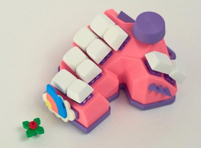
There are few buttons, the design and code are optimized to be straightforward and easy to modify, and the interface is slick. Eight musical keys complement three interface keys and a knob. An Arduino Nano powers the main brains of the system but the music generation comes from eight Nuvoton ISD1700s controlled over SPI by the Nano. The beautifully laid-out PCB is 110mm by 180mm (4.33″ by 7″), so cases can easily be printed on smaller FDM printers. All the switches are Cherry MX switches for the beautiful tactile feedback.

The code, PCB, and 3D case files are all available on GitHub. We love the thought that went into the design and the focus on making it easy to recreate. It might be quite as cute and simplified as this twelve-button musical macro pad, but the two together could make quite the band.

Continue reading “ISD1700 Based Lo-Fi Sampler”

Holograms: The Future Of Speedy Nanoscale 3D Printing?

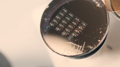
3D printing by painting with light beams on a vat of liquid plastic was once the stuff of science fiction, but now is very much science-fact. More than that, it’s consumer-level technology that we’re almost at the point of being blasé about. Scientists and engineers the world over have been quietly beavering away in their labs on the new hotness, nanoscale 3D printing with varying success. Recently IEESpectrum reports some promising work using holographic imaging to generate nanoscale structures at record speed.

Current stereolithography printers make use of UV laser scanned over the bottom of a vat of UV-sensitive liquid photopolymer resin, which is chemically tweaked to make it sensitive to the UV frequency photons. This is all fine, but as we know, this method is slow and can be of limited resolution, and has been largely superseded by LCD technology. Recent research has focussed on two-photon lithography, which uses a resin that is largely transparent to the wavelength of light concerned, but critically, can be polymerized with enough energy density (i.e. the method requires multiple photons to be simultaneously absorbed.) This is achieved by using pulsed-mode lasers to focus to a very tight point, giving the required huge energy density. This tight focus, plus the ability to pass the beam through the vat of liquid allows much tighter image resolution. But it is slow, painfully slow.

Continue reading “Holograms: The Future Of Speedy Nanoscale 3D Printing?”

Russia’s New Mystery Shortwave Station

The Buzzer, also known as UVB-76 or UZB-76, has been a constant companion to anyone with a shortwave radio tuned to 4625 kHz. However, [Ringway Manchester] notes that there is now a second buzzer operating near in frequency to the original. Of course, like all mysterious stations, people try to track their origin. [Ringway] shows some older sites for the Buzzer and the current speculation on the current transmitter locations.

Of course, the real question is why? The buzzing isn’t quite nonstop. There are occasional voice messages. There are also jamming attempts, including one, apparently, by Pac Man.

Some people think the new buzzer is an image, but it doesn’t seem to be the same signal. The theory is that the buzzing is just to keep the frequency clear in case it is needed. However, we wonder if it isn’t something else. Compressed data would sound like noise.  Other theories are that the buzzing studies the ionosphere or that it is part of a doomsday system that would launch nuclear missiles. Given that the signal has broken down numerous times, this doesn’t seem likely.

What’s even stranger is that occasional background voices are audible on the signal. That implies that buzzing noise isn’t generated directly into the transmitter but is a device in front of a microphone.

We’ve speculated on the buzzer and the jamming efforts around it before. Not exactly a numbers station, but the same sort of appeal.

Continue reading “Russia’s New Mystery Shortwave Station”

Photoplotting PCBs With A 3D Printer

Do you ever wonder why your PCB maker uses Gerber files? It doesn’t have to do with baby food. Gerber was the company that introduced photoplotting. Early machines used a xenon bulb to project shapes from an aperture to plot on a piece of film. You can then use that film for photolithography which has a lot of uses, including making printed circuit boards. [Wil Straver] decided to make his own photoplotter using a 3D printer in two dimensions and a UV LED. You can see the results in the video below.

A small 3D printed assembly holds a circuit board, the LED, and a magnet to hold it all to the 3D printer. Of course, an LED is a big large for a PCB trace, so he creates a 0.3 mm aperture by printing a mold and using it to cast epoxy to make the part that contacts the PCB film.

Continue reading “Photoplotting PCBs With A 3D Printer”