Jumbo LEDs Make For A Handy ATtiny Beacon

Inspiration can come from anywhere. Sometimes it’s just a matter of seeing an interesting part that you want to fiddle around with badly enough that you end up developing a whole idea, and potentially product, around it. That’s how [Bobricius] found himself creating this very slick little warning beacon, and looking at the end result, we think he made the right decision.

The Kingbright DLC-6SRD “jumbo” LED is actually six individual emitters built into a plastic diffuser. Interfacing with the device is simple enough; each LED has its normal anode and cathode leg, all you need to do is power them up. What [Bobricius] has created is a simple PCB design that the DLC-6SRD can plug right into, complete with a 2032 coin cell holder on the opposite side.

Of course, just lighting up all six elements at the same time wouldn’t be very interesting. [Bobricius] is controlling them individually right off of the digital pins of an ATtiny10 with the help of some Charlieplexing. This makes all kinds of interesting patterns possible, and as demonstrated in the video after the break, the current iteration of the project uses some very simple code to “rotate” the LED as if it was the flasher on an emergency vehicle.

The addition of a few blinking LEDs can make a world of difference in terms of nighttime visibility, so a cheap stick-on module that adds such a distinctive light pattern could be a very important safety device. It could also be useful for UAVs, following the FAA’s new rules which would mandate anti-collision lights for night flying.

Continue reading “Jumbo LEDs Make For A Handy ATtiny Beacon”

Get Twelve Charlieplexed PWM Outputs From An ATtiny85

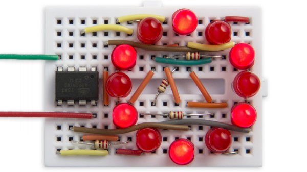
Most of us are aware that charlieplexing can drive a large number of LEDs from a relatively small number of I/O pins, but [David Johnson-Davies] demonstrates adding another dimension to that method to create individually controlled PWM outputs as well. His ATtiny85 has twelve LEDs, each with individually-set brightness levels, and uses only four of the five I/O pins on the device.

Each LED can be assigned a brightness between 0 (fully off) and 63 (fully on). The PWM is done by using one of the timers in the ATtiny85 to generate a periodic interrupt, and the ISR for the interrupt takes care of setting the necessary ratios of on and off times for each charlieplexed output. The result? Twelve flicker-free LEDs with individually addressable brightness levels, using an 8-pin microcontroller and just a few passive components on a tiny breadboard. There’s even one I/O pin left on the ATtiny85, for accepting commands or reading a sensor.

[David] really wrings a lot out of the ATtiny series of microcontrollers with his compact projects, like his Tiny Function Generator (which recently got an update.) He also demonstrated that while charlieplexing is usually used with LEDs, charlieplexing can be used with switches just as easily.

A Tiny IDE For Your ATtiny

When writing code for the ATtiny family of microcontrollers such as a the ATtiny85 or ATtiny10, people usually use one of two methods: they either add support for the chip in the Arduino IDE, or they crack open their text editor of choice and do everything manually. Plus of course there are the stragglers out there using Eclipse. But [Wayne Holder] thinks there’s a better way.

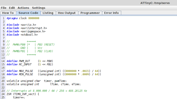
The project started out as a simple way for [Wayne] to program the ATtiny10 in C under Mac OS, but has since evolved into an open source, cross-platform integrated development environment (IDE) for programming a wide range of ATtiny chips in C, C++, or Assembly. Not only does it integrate the source code editor and programmer, but it even bundles in documentation for common variants of the chips including block diagrams and pinouts; making it a true one-stop-shop for ATtiny hacking.

His IDE runs under Java, including OpenJDK, and [Wayne] provides a stable pre-built executable for those who don’t want to clone the whole GitHub repository. He’s included the GNU/AVR toolchains, though notes that testing so far has been limited to Mac OS, and he’s interested in feedback from Windows and Linux users. Assembly is done either with GNU AVR-AS, or an assembler of his own design, though the latter is currently limited to the ATTiny10.

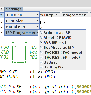
To actually get the code onto the chip, the IDE supports using the Arduino as a programmer as well as dedicated hardware like the BusPirate or the USBasp. If you go the Arduino route, [Wayne] has even come up with a little adapter board which he’s made available through OSH Park to help wrangle the diminutive chips.

The ATtiny10 might have something of a learning curve, but in exchange this family of tiny microcontrollers offers an incredible amount of capability. When you’re working with what’s essentially a programmable grain of rice, the only limit is your own creativity.

Building And Controlling 19 LEDs & Five Buttons From Five Outputs

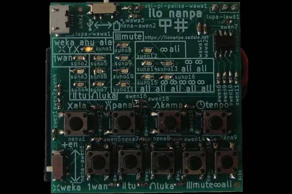
Numbers are hard enough in English, but [Sadale] decided to take things a step further by building a calculator that works in Toki Pona. The result is Ilo Nanpa, an awesome hardware calculator that works in this synthetic minimal language. This is a bit harder than you might think, because Toki Pona doesn’t have digits in the same way that Neo-Latin languages like English do. Instead, you combine smaller numbers to make bigger ones. One is Wan, Two is Tu, but three is Wan Tu (1+2). As you might expect, this makes dealing and representing larger numbers somewhat complicated.

Ilo Nanpa gets around this in a wonderfully elegant way, and with some impressive behind the scenes work. The calculator has 16 LEDs, nine buttons and a slider switch, but they are all controlled and read through just five IO pins on the STM8S001J3 controller that runs the device.

That’s because {Sadale] did some remarkable work with multiplexing and charlieplexing. Multiplexing is controlling more outputs than there are control inputs by using rows and columns: it is how the LED display you are probably reading this on can be controlled by just a few wires. By switching through these rows and columns at a higher speed than the eye can see, you create the illusion of a single, continuous display.

Charlieplexing takes this a step further by using multiple voltages on a single connection to further split the signal. With the clever use of voltage dividers the directional properties of LEDs and multiple voltage levels, the Ilo Nanpa runs all of the LEDs and senses all of the buttons and the slider from just five pins. That’s a remarkably neat piece of design, and it is worth spending some time looking over the excellent explanation of the process that [Sadale] wrote to see how it is done, and poring over the code for the device to see how he programmed this all into a single low powered chip. And, while you are reading, you might pick up a few words of Toki Pona. Tawa Pona!

Continue reading “Building And Controlling 19 LEDs & Five Buttons From Five Outputs”

Advances In Flat-Pack PCBs

Right now, we’ve got artistic PCBs, we’ve got #badgelife, and we have reverse-mounted LEDs that shine through the fiberglass substrate. All of this is great for PCBs that are functional works of art. Artists, though, need to keep pushing boundaries and the next step is obviously a PCB that doesn’t look like it has any components at all. We’re not quite there yet, but [Stephan] sent in a project that’s the closest we’ve seen yet. It’s a PCB where all the components are contained within the board itself. A 2D PCB, if you will.

[Stephen]’s project is somewhat simple as far as a #badgelife project goes. It’s a Christmas ornament, powered by two coin cells, hosting an ATTiny25 and blinking two dozen LEDs via Charlieplexing. The PCB was made in KiCAD, with some help from Inkscape and Gimp. So far, so good.

Castellated edges, containing a part

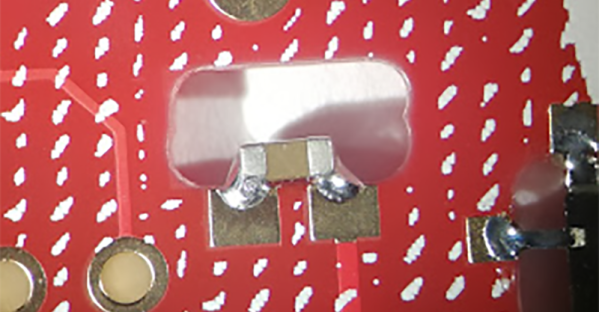
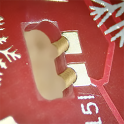
The trick is mounting all the components in this project so they don’t poke out above the surface of the board. This is done by milling a rectangular hole where every part should go and adding castellated pads to one side of the hole. The parts are then soldered in one at a time against these castellated pads, so the thickness of the completed, populated board is just the thickness of the PCB.

The parts used in this project are standard jellybean parts, but there are a few ways to improve the implementation of this project. The LEDs are standard 0805s, but side-emitting LEDs do exist. If you’d like to take this idea further, it could be possible to create a sandwich of PCBs, with the middle layer full of holes for components. These layers of PCBs can then be soldered or epoxied together to make a PCB that actually does something, but doesn’t look like it does. This technique is done in extremely high-end PCBs, but it’s expensive as all get out.

Still, this is a great example of what can be done with standard PCB processes and boards ordered from a random fab house. It also makes for a great Christmas ornament and pushes the boundaries of what can be done with PCB art.

Less Is More: A Micromatrix Display In A Square Inch

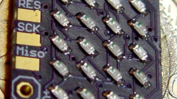
In your living room, the big display is what you want. But in an embedded project, often less is more. We think [bobricius] will agree since he submitted a tiny 4×5 LED display into our square inch challenge. The board features an ATtiny CPU and twenty SMD LEDs in a nice grid. You can see them in action, scrolling to some disco music in the video below.

There is plenty of room left in the CPU for bigger text strings — the flash memory is just over 10% full. A little side-mounted header makes it easy to program the chip if you want to change anything.

Continue reading “Less Is More: A Micromatrix Display In A Square Inch”

The A To Z Of Building Your Own Keyboard

We’ve featured a number of people who’ve taken the plunge and created their own customized keyboard; at this point it’s safe to say that there’s enough information and source code out there that anyone who’s looking to build their own board won’t have much trouble figuring out how to do so. That being said, it’s nice to have a comprehensive at a process from start to finish. Why sift through forum posts and image galleries looking for crumbs if you don’t have to?

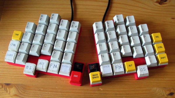
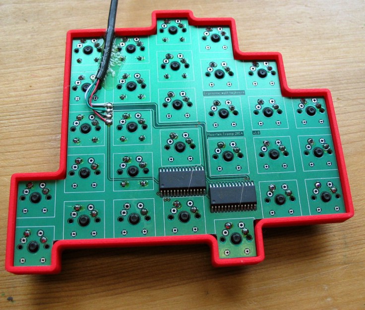
That’s precisely what makes this write-up by [Maarten Tromp] so interesting. He walks the reader through every step of the design and creation of his customized keyboard, from coming up with the rather unique layout to writing the firmware for its AVR microcontroller. It’s a long read, filled with plenty of tips and tricks from a multitude of disciplines.

After looking at other custom boards for inspiration, [Maarten] used OpenSCAD to create a 3D model of his proposed design, and had it printed at Shapeways. His electronics are based around an Atmel ATMega328P using vUSB, and Microchip MCP23017 I/O expanders to connect all the keys. He wrapped it all up by designing a PCB in gEDA PCB and having it sent off for production. As a testament to his attention to detail, everything mated up on the first try.

[Maarten] is happy with the final product, but mentions that in a future revision he would like to add RGB lighting and use a microcontroller that has native USB support. He’d also like to drop the I/O expanders and switch over to Charlieplexing for the key matrix.

From uncommon layouts to diminutive technicolor beauties, it seems there’s no end of custom keyboards in sight. We aren’t complaining.