A Fantastic Frontier Of FPGA Flexibility Found In The 2019 Supercon Badge

We have just concluded a successful Hackaday Superconference where a highlight for many was digging into this year’s hardware badge. Shaped in the general form of a Game Boy handheld gaming console, the heart of the badge is a large FPGA opening up new and exciting potential for badge hacking.

Beyond our normal tools of compiling custom code or modifying hardware with a soldering iron, we now have the option to change core hardware behavior with Verilog. And people explored this new frontier to great effect, as seen at the badge hacking ceremony. (Video embedded below.)

FPGAs are not new, technically speaking, why are they exciting now? We can thank their recent growth in capability, their rapidly falling cost, and the relatively new availability of open source toolchains. These developments elevated FPGA into one of the most exciting trends in hardware today, so this year’s badge master [Sprite_TM] built an open FPGA playground for several hundred of his closest Supercon friends. Let’s take a look at what people were able to accomplish in just a few days using this unique and powerful hardware.

Continue reading “A Fantastic Frontier Of FPGA Flexibility Found In The 2019 Supercon Badge”

A Self-Expanding PWM Driver

For smaller microcontrollers, having enough outputs for the job is sometimes a challenge. A common solution is to do some sort of multiplexing with the available outputs or perhaps something more advanced such as Charlieplexing, but another good option is to use a specialized driver board. What’s even better is if you can daisy chain driver boards to get even more outputs.

[Eric] has been working on a 16 channel LED project but first wanted to build a driver board with 8 channels. Before building a full 16 channel version he realized that he could take the same 8 channel board, make a mirror image of it, and attach it underneath the first board with headers in order to double the number of channels available. Without having to build a separate 16-channel board, this shortcut saved [Eric] some time and a great deal of effort.

This is a great example of working smarter, not harder. Each of the 8 or 16 channels has full PWM support as well to support PWM dimming, and a similar board could be built for motor control as well. It’s a good illustration of how good design can end up working for you as well. And if you need even more outputs, Charlieplexing is one way to get them.

Continue reading “A Self-Expanding PWM Driver”

The Basics Of Persistence Of Vision Projects

Persistence of Vision (POV) is a curious part of the human visual system. It’s the effect by which the perception of an image lingers after light has stopped entering the eye. It’s why a spinning propeller appears as a disc, and why a burning sparkler appears to leave a trail in the air. It’s also commonly used as a display technology, where a series of flashing LEDs can be used to create messages that appear to float in the air. POV displays are a popular microcontroller project, and today, we’ll explore the basic techniques and skills required in such builds.

Continue reading “The Basics Of Persistence Of Vision Projects”

Beam Me Up To The PCB Space Ship

This project would fit in perfectly with #BadgeLife if someone could figure out a way to hang it from their neck. Inspired by Star Trek’s Starship Enterprise, [bobricius] decided to design and assemble a miniature space ship PCB model, complete with 40 blinking LEDs controlled by an ATtiny85.

While the design uses 0603, 0802, 3014, 4014, and 0805 LEDs, some substitutions can be made since the smallest LEDs can be difficult to solder. The light effects include a green laser, plasma coils, a deflector with scrolling blue LEDs, and the main plate and bridge for the space ship.

The LEDs are controlled by charlieplexing, a technique for driving LED arrays with relatively few I/O pins, different from traditional multiplexing. Charlieplexing allows n pins to drive n2−n LEDs, while traditional multiplexing allows n pins to drive (n/2)2 LEDs. (Here is the best explanation of Charlieplexing we’ve ever seen.)

Especially with the compiled firmware running on the MCU, the PCB model makes for an impressive display.

The only catch? Your Starship Enterprise can’t actually fly.

Continue reading “Beam Me Up To The PCB Space Ship”

Returning Digital Watches To The Analog Age: Enter The Charliewatch

The Charliewatch by [Trammell Hudson] is one of those projects which is beautiful in both design and simplicity. After seeing [Travis Goodspeed]’s GoodWatch21 digital watch project based around a Texas Instruments MSP430-based SoC, [Trammell] decided that it’d be neat if it was more analog. This is accomplished using the CC430F5137IRGZR (a simpler member of the MSP430 family) and a whole bunch of 0603 SMD LEDs which are driven using Charlieplexing.

This time-honored method of using very few I/O pins to control many LEDs makes it possible to control 72 LEDs without dedicating 72 pins. The density makes animations look stunning and the digital nature melts away leaving a distinct analog charm.

A traditional sapphire crystal was sourced from a watchmaker for around 14€ as was the watch band itself. The rest is original work, with multiple iterations of the 3D printed case settling in on a perfect fit of the crystal, PCB, and CR2032 coin cell stackup. The watch band itself hold the components securely in the housing, and timekeeping is handled by a 32.768 kHz clock crystal and the microcontroller’s RTC peripheral.

The LEDs can be seen in both daylight and darkness. The nature of Charlieplexing means that only a few of the LEDs are ever illuminated at the same time, which does wonders for battery life. [Trammell] tells us that it can run for around six months before the coin cell needs replacing.

It’s completely open source, with project files available on the project’s Github page. We hope to see an army of these watches making appearances at all upcoming electronics-oriented events. Just make sure you lay off the caffeine as the process of hand-placing all those LEDs looks daunting.

Visualizing LEDs For More Efficient Pin Packing

The archetypal “blink an LED” is a great starter project on any platform, but once the bug takes hold that quickly turns into an exploration of exactly how many LEDs a given microcontroller can drive. And that often leads to Charlieplexing. A quick search yields many copies of The Table describing how many LEDs can be driven by a given number of pins but that’s just the most rudimentary way to describe it. Way back in 2013 [M Rule] developed a clever trick to describe the number of LED matrices which can be driven by a Charlieplexed array of a given size that makes this process much more intuitive. The post may be old, but we promise the method is still fresh.

[M Rule] was specifically looking to drive those big, cheap single color LED matrices which are often used to make scrolling signs and the like. These parts are typically a matrix of LEDs with a row of common cathodes and one of common anodes. Internally they are completely dumb and can be driven by row/column scanning, or any other way a typical matrix can be controlled. The question is, given known matrix sizes, how many can be driven with a a number of Charlieplexed LED drive pins?

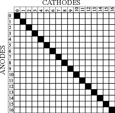
The first step is to visualize the 1D array of available pins as a 2D matrix, as seen to the right. Note each numbered pin is the same on the X and Y, thus the black exclusion zone of illegal drive pin combinations slicing across the graph (you can’t drive an LED connected to one pin twice). The trick, if one were to say it resides in a single place, would be titling the axis anode and cathode, representing two “orientations” the drive pins can be put in. With this diagram [M Rule] observed you can simply drop a matrix into the array. If it fits outside the exclusion zone, it can be driven by those pins!

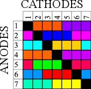
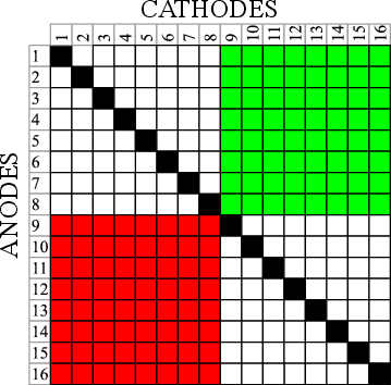
To the left is what this looks like with two 8×8 matrices, one connected between pins 1-8 and 9-16, the other connected between 9-16 and 1-8. This isn’t terribly interesting, but the technique works just as well with single LEDs and any size matrix, including 7-segment displays. Plus as long as an element doesn’t overlap itself it can wrap around the edges leading to some wild visuals, like 14 RGB LEDs on seven pins to the right.

The most extreme examples are pretty exotic. Check out [M Rule]’s post for the crown jewel; 18 pins to drive six 5×7 modules, six 7-segment displays, 12 single LEDs, and 18 buttons!

If this color coded diagram seems familiar, you may be remembering [openmusiclabs]’ excellent diagram describing ways to scan many of buttons. Or our coverage of another trick of matrix topology by [M Rule] from a few weeks ago.

Hackaday Podcast 020: Slaying The Dragon Of EL, Siege Weapon Physics, Dis-entangled Charlieplex, Laser Internet

Join editors Elliot Williams and Mike Szczys as they unpack all the great hacks we’ve seen this week. On this episode we’re talking about laser Internet delivered from space, unwrapping the complexity of Charlieplexed circuits, and decapping ICs both to learn more about them and to do it safely at home. We have some fun with backyard siege weapons (for learning about physics, we swear!), gambling on FPGAs, and a line-scanning camera that’s making selfies fun again. And nobody thought manufacturing electroluminescent displays was easy, but who knew it was this hard?

Take a look at the links below if you want to follow along, and as always, tell us what you think about this episode in the comments!

Take a look at the links below if you want to follow along, and as always, tell us what you think about this episode in the comments!

Direct download (60 MB or so.)

Continue reading “Hackaday Podcast 020: Slaying The Dragon Of EL, Siege Weapon Physics, Dis-entangled Charlieplex, Laser Internet”