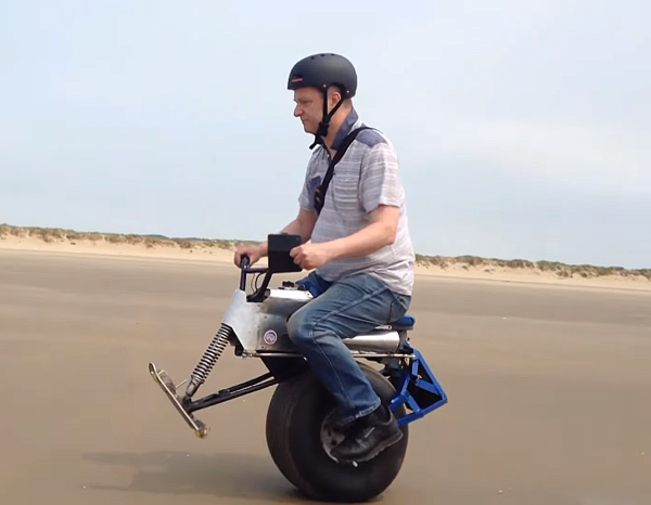
[XenonJohn] wrote in to let us know about updates and a recent test drive of an Electric Self-Balancing One-wheeled Motorcycle, fresh from the beach where he says it proved to be great fun to ride. The design and build have been updated since we last saw it as a semifinalist entry in the 2014 Hackaday Prize. The original, he says, “looked cool but was slow, cumbersome and really dangerous to ride.”
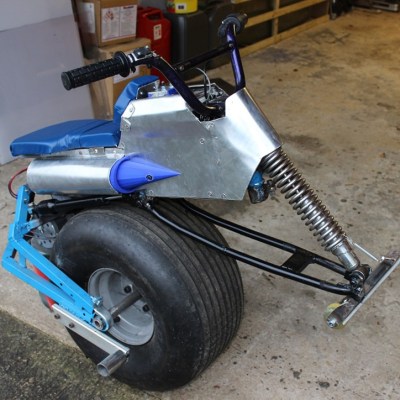 Since then it has been completely redesigned and now has a super fat kite-surfer wheel, a front crash skid with damper, and a variable geometry which allows it to steer properly despite just having one wheel. It does this by allowing the rider to shift their position relative to the wheel, instead of the seat always being rigidly locked directly above the axle.
That steering is a pretty clever upgrade, but we do wonder if the new crash skid will have an atlatl effect and really launch the rider in a crash. Our gut feeling aside, it is designed not to plant itself in the pavement, but to slide along (without ejecting the rider) until the vehicle loses all momentum.
There is something about self-balancing unicycles that attracts experimenters, each of whom takes a different approach. We see everything from this device constructed mainly from a Razor Scooter to this more polished-looking unit based on an earlier Segway clone design. [XenonJohn] reminds us that “there is still much to learn in this area and you can genuinely innovate even as a hobbyist. Also, you can only do so much on a computer, you then have to actually build something and see how well it works. [This recent test] shows what you can do if you just keep on experimenting.” Video of the test drive is below.
Continue reading “Self-Balancing One-Wheel Motorcycle Tears Up The Beach”