The Practical Approach To Keeping Your Laser In Focus

You could be forgiven for thinking that laser cutters and engravers are purely two dimensional affairs. After all, when compared to something like your average desktop 3D printer, most don’t have much in the way of a Z axis: the head moves around at a fixed height over the workpiece. It’s not as if they need a leadscrew to push the photons down to the surface.

But it’s actually a bit more complicated than that. As [Martin Raynsford] explains in a recent post on his blog, getting peak performance out of your laser cutter requires the same sort of careful adjustment of the Z axis that you’d expect with a 3D printer. Unfortunately, the development of automated methods for adjusting this critical variable on lasers hasn’t benefited from the same kind of attention that’s been given to the problem on their three dimensional counterparts.

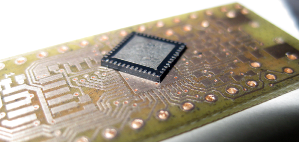
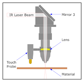
Ultimately, it’s a matter of focus. The laser is at its most powerful when its energy is concentrated into the smallest dot possible. That means there’s a “sweet spot” in front of the lens where cutting and engraving will be the most efficient; anything closer or farther away than that won’t be as effective. As an example, [Martin] says that distance is exactly 50.3 mm on his machine.

The problem comes when you start cutting materials of different thicknesses. Just a few extra millimeters between the laser and your target material can have a big difference on how well it cuts or engraves. So the trick is maintaining that perfect distance every time you fire up the laser. But how?

One way to automate this process is a touch probe, which works much the same as it does on a 3D printer. The probe is used to find where the top of the material is, and the ideal distance can be calculated from that point. But in his experience, [Martin] has found these systems leave something to be desired. Not only do they add unnecessary weight to the head of the laser, but the smoke residue that collects on the touch probe seems to invariably mar whatever surface you’re working on with its greasy taps.

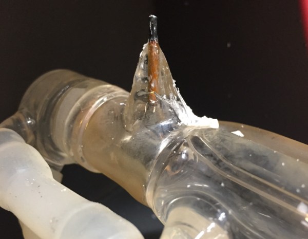
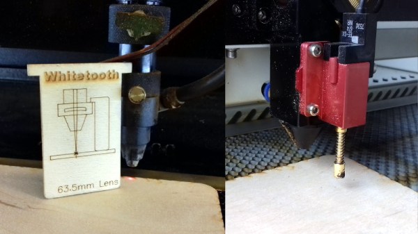
In his experience, [Martin] says the best solution is actually the simplest. Just cut yourself a little height tool that’s precisely as long as your laser’s focal length. Before each job, stick the tool in between the laser head and the target to make sure you’re at the optimal height.

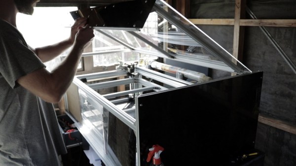
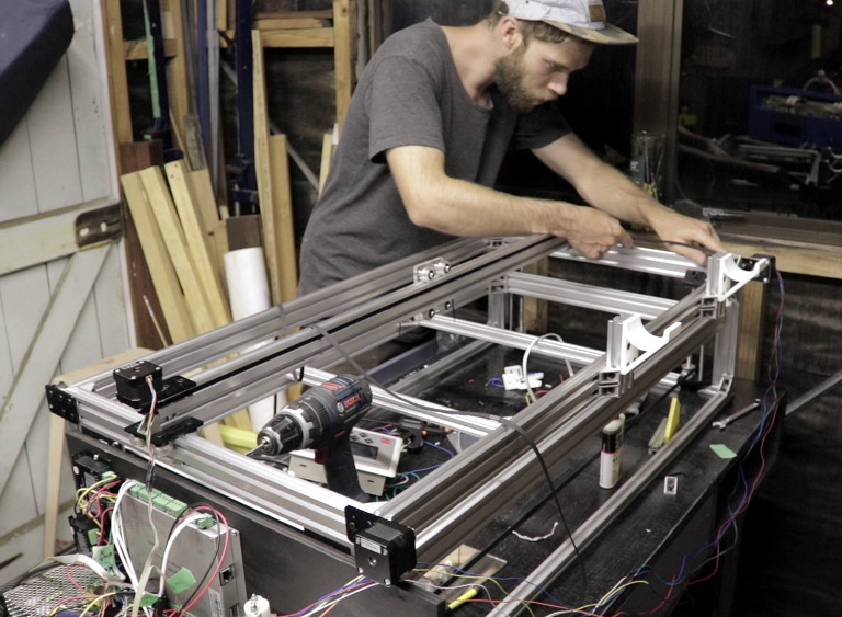
On entry level lasers, adjusting the Z height is likely to involve turning some screws by hand. But you can always add a motorized Z table to speed things up a bit. Of course, you’ll still need to make sure your X and Y alignment is correct. Luckily, [Martin] has some tips for that as well.

Hackaday Podcast 005: Undead Lightbulbs, Home Chemistry, And The Strength Of 3D Printing

Catch up on interesting hacks from the past week with Hackaday Editors Mike Szczys and Elliot Williams. This week we discuss the story behind falling lifetime ratings for LED bulbs, look at finite element analysis to strengthen 3D printed parts, admire the beauty of blacksmithing, and marvel at open source Lidar development. We delve into great reader suggestions for Blue Pill projects sparked by last week’s podcast, discuss some history of the V2 rocket, and cover Chromecast control hardware, glowing home chemistry, K40 laser cutter add-ons, and more.

Links for all discussed on the show are found below. As always, join in the comments below as we’ll be watching those as we work on next week’s episode!

Take a look at the links below if you want to follow along, and as always, tell us what you think about this episode in the comments!

Direct download (60 MB or so.)

Continue reading “Hackaday Podcast 005: Undead Lightbulbs, Home Chemistry, And The Strength Of 3D Printing”

Hackaday Podcast: 2018 Year In Review

Did you read all 3000+ articles published on Hackaday this year? We did. And to help catch you up, we preset the Hackaday 2018 Year in Review podcast!

Join us for the podcast, available on all major podcasting platforms, as Editors Mike Szczys and Elliot Williams attempt the impossible task of distilling the entire year into a one hour discussion. We’ve included every story mentioned in the podcast, and a few more, in the show notes here. But since we can’t possibly mention every awesome hack, we encourage you to share your favorites, and pat the writers on the back, by leaving a comment below.

Take a look at the links below if you want to follow along, and as always, tell us what you think about this episode in the comments!

Direct download (60 MB or so.)

Continue reading “Hackaday Podcast: 2018 Year In Review”

Fail Of The Week: Did My Laser Cutter Tube Really Burn Out?

All the cool kids are doing it these days, or more like for many years now: you can get a laser cutter for a song if you don’t mind doing your own repairs and upgrades — you know, being a hacker. The downside is that some failures can really ruin your day. This is what [Erich Styger] encountered with his cutter that is just a bit more than a year old. This Fail of the Week looks at the mysterious death of a CO2 laser tube.

This is the infamous K40 laser cutter. Our own [Adam Fabio] just took one on a couple of months back and [Erich] even references Hackaday coverage of the K40 Whisperer project as what pushed him over the edge to make the purchase. We’ve followed his blog as he acquired the cutter and made upgrades along the way, but after an estimated 500 hours of use, a horrible teeth-gnashing screech sprung forth from the machine. [Erich’s] reaction was to hit the e-stop; that’s certainly why it’s there.

Chasing down the problem is a story well-told, but as is often the case with these FotW articles, in the end what caused the failure is not entirely known. We’d love to hear what you think about it in the comments below.

The investigation began at the power supply for the laser, but that didn’t yield any answers. Next he moved to the tube itself, noticing that the wire connection to the tube’s anode wasn’t soldered. The anode is an unknown material he suspects to be graphite and he found a video showing the “soldering” process for connecting a wire. (We added quotes to that as the video he linked doesn’t actually solder anything but the wrapped wire strands themselves.) The solution he found is a great tip to take away from the story. It’s a socket by TE Connectivity to which he soldered the wire. Assuming it’s power rated for the task, and won’t fall off during normal operation, this is a great way to do it.

But we digress. Even with the connection made, the old tube had to be replaced with a new one. It’s also notable that the portion of that anode inside the bad tube is orange in color when a new tube would be black like the part on the outside. Does this hint at why that tube died, and could this have been avoided? If you have insight, help us learn from this failure by leaving a comment below.

Scratch-Building A Supersized Laser Cutter

Now that 3D printers have more or less hit the mass market, hackers need a new “elite” tool to spend their time designing and fiddling with. Judging by the last couple of years, it looks like laser cutters will be taking over as the hacker tool du jour; as we’re starting to see more and more custom builds and modifications of entry-level commercial models. Usually these are limited to relatively small and low powered diode lasers, but as the following project shows, that’s not always the case.

This large format laser cutter designed and built by [Rob Chesney] is meticulously detailed on his blog, as well as in the in the video after the break. It’s made up of aluminium profile and a splattering of ABS 3D printed parts, and lives in an acrylic enclosure that’s uniquely isolated from the laser’s internal gantry. All told it cost about $2,000 USD to build, but considering the volume and features of this cutter that’s still a very fair price.

[Rob] carefully planned every aspect of this build, modeling the entire machine in CAD before actually purchasing any hardware. Interestingly enough his primary design constraint was the door to his shed: he wanted to build the largest possible laser cutter that could still be carried through it. That led to the final machine’s long and relatively shallow final dimensions. The design was also guided by a desire to minimize material waste, so when possible parts were designed to maximize how many could be cut from a one meter length of aluminum extrusion.

The laser features a movable Z axis that’s similar in design to what you might see in a Prusa-style 3D printer, with each corner of the gantry getting an 8 mm lead screw and smooth rod which are used in conjunction to lift and guide. All of the lead screws are connected to each other via pulleys and standard GT2 belt, but as of this version, [Rob] notes the Z axis must be manually operated. In the future he’ll be able to add in a stepper motor and automate it easily, but it wasn’t critical to get the machine running.

He used 3D printed parts for objects which had a relatively complex geometry, such as the laser tube holders and Z axis components, but more simplistic brackets were made out of cut acrylic. In some components, [Rob] used welding cement to bond two pieces of acrylic and thereby double the thickness. Large acrylic panels were also used for the laser’s outer enclosure, which was intentionally designed as a separate entity from the laser itself. He reasoned that this would make assembly easier and faster, as the enclosure would not have to be held to the same dimensional tolerances as it would have been if it was integrated into the machine.

[Rob] gives plenty of detail about all the finer points of water cooling, laser control electronics, aligning the mirrors, and really anything else you could possibly want to know about building your own serious laser cutter. If you’ve been considering building your own laser and have anything you’re curious or unsure about, there’s a good chance he addresses it in this build.

Short of having the fantastically good luck to find a laser cutter in the trash that you can refurbish, building your own machine may still be the best upgrade path if you outgrow your eBay K40.

Continue reading “Scratch-Building A Supersized Laser Cutter”

Fail Of The Week: When The Epoxy-Coated Chip Is Conductive

Every once in a while, you’ll find some weirdness that will send your head spinning. Most of the time you’ll chalk it up to a bad solder joint, some bad code, or just your own failings. This time it’s different. This is a story of weirdness that’s due entirely to a pin that shouldn’t be there. This is a package for an integrated circuit that has a pin zero.

The story begins with [Erich] building a few development boards for the Freescale Kinetis K20 FPGA. This is a USB-enabled microcontroller, and by all accounts, a worthwhile effort. So far, so good. The problem with the prototype boards was soon apparent. On some of the boards, the external 32 kHz oscillator was not starting. Resoldering the oscillator or microcontroller sometimes solved the problem, but not always. This is troubling, because that means the issue isn’t code, and it’s not the PCB. This is going to take a deep dive and a good inspection microscope.

One of [Erich]’s friends, [Christian B] somehow found the problem. When the Freescale K40 is manufactured, the die is carefully laid in a chip carrier and coated with epoxy, putting it in a small QFN package. The problem is, there’s an extra connection sticking out of one corner of this chip. This is just an artifact of the chip carrier, but if you leave exposed metal connected to ground, something is eventually going to go wrong.

The best guess [Erich] has is that this additional connection is from the manufacturing and packaging process, with the exposed metal pad in this application being bridged to an adjacent pad. Now, if there’s one failure to [Erich]’s design, it’s that the trace comes out of the pin on the adjacent pad at 90 degrees; this isn’t a best practice, but most of the time you can get away with it. This time, though, somebody got burned.

We don’t know how [Christian] ever found this issue. When you look at a tiny QFN package, you don’t expect there to be an extra pin attached to ground that can be easily bridged with a bit of solder paste. It’s either a lot of luck or skill to find this problem, but it’s a great example of the weird things you have to look out for.

Hackaday Links Column Banner

Hackaday Links: November 18, 2018

The greatest bit of consumer electronics is shipping and the reviews are out: Amazon’s Alexa-enabled microwave is a capable microwave, but befuddling to the voice-controlled-everything neophyte. Voice controlled everything is the last hope we have for technological innovation; it’s the last gasp of the consumer electronics industry. This is Amazon’s first thing with a built-in voice assistant, and while this is a marginally capable microwave at only 700 Watts — fine for a college dorm, but it’s generally worth shelling out a bit more cash for a 1000 Watt unit — the controls are befuddling. The first iteration is always hard, and we’re looking forward to the Amazon Alexa-enabled toaster, toothbrush, vacuum cleaner, and Bezos shrine.

Need a laser cutter, like crowdfunding campaigns, and know literally nothing about laser cutters? Have we got something for you. The Etcher Laser crowdfunding campaign has been pinging my email non-stop, and they’ve got something remarkable: a diode laser cutter engraver for $500. It comes in a neat-looking enclosure, so it’s sure to raise a lot of money.

A while back [Paulusjacobus] released an Arduino-based CNC controller for K40 laser cutters. There were a few suggestions to upgrade this to the STM32, so now this CNC controller is running on a Blue Pill. Yes, it’s great and there’s more floating points and such and such, so now this project is a Kickstarter project. Need a CNC controller based on the STM32? Boom, you’re done. It’s also named the ‘Super Gerbil’, which is an awesome name for something that is effectively a GRBL controller. Naming things is the hardest problem in computer science, after all.

The Gigatron computer is a ‘home computer’ without a microprocessor or microcontroller. How does it do this? A metric butt-load of ROM and look-up tables. This is cool and all, but now the Gigatron logo is huge. we’re talking 18 μm by 24 μm. This was done by etching a silicon test wafer with electron beam lithography.