One Dimensional PONG Is A Great Use For LED Strips

[Jason] has had a five meter addressable RGB LED strip lying around for a while, and only recently came up with a good idea of what to use it for. He came up with One Dimensional PONG, and it looks like it’s a blast to play. Instead of moving a paddle up and down, [Jason]’s 1D PONG game requires the players to stomp on a switch to send the ball back to the other player.

The LED strip [Jason] used has an SPI interface, but needed to be PWM clocked to a microcontroller to operate. After whipping up an Arduino library for his LED strip, [Jason] built an ATMega328-based controller board and a pair of seven segment display boards to keep track of the score. There’s a technical overview in another one of [Jason]’s videos.

[Jason] will be taking his 1D PONG game to the Brighton Mini Maker Faire on September 8th. We’re sure his game will be very popular there, so if you see him, tell him Hackaday sent you.

Continue reading “One Dimensional PONG Is A Great Use For LED Strips”

Time And Date Clock Does It With RGB LED Strips

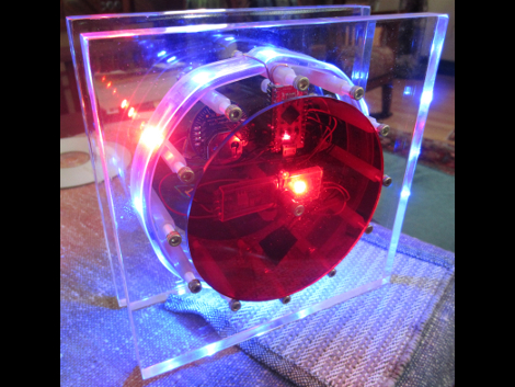
[Craig’s] color clock really came together quite nicely. The majority of the body is acrylic, with two large clear squares and a pair of colored discs. All are held in place by a ring of hardware with spacers in them, and the RGB LED strip that is used to display time and date wraps around those spacers. This hides the components in the center, with a USB cord connecting to the Arduino compatible board to power the device.

Hours are displayed in red, with minutes shown in green, and blue used as a background color. In the center you can see one of two red LEDs which alternate like a pendulum to mark the passing seconds. There are timed events every ten , fifteen, and thirty minute. At the fifteen minute mark the clock switches to display the date. The other two events are animations to keep things interesting. All of the settings for the clock are accessed using just two momentary push buttons mounted on the back of the clock.

Continue reading “Time And Date Clock Does It With RGB LED Strips”

Stair Accent Lights Made From Cheap LED Strips

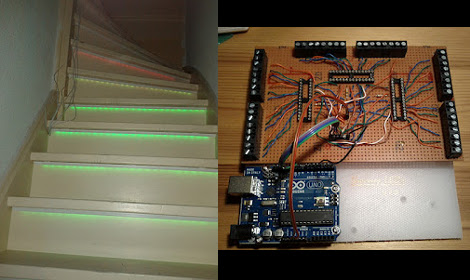
We really like [Geert’s] take on accent lighting for his stairs. He built his own LED channels which mount under the bullnose of each step. The LED strips that he used are actually quite inexpensive. They are RGB versions, but the pixels are not individually addressable. This means that instead of having drivers integrated into the strip (usually those use SPI for color data) this strip just has a power rail and three ground rails for the colors. Ten meters of the strip cost him under forty dollars.

He did want to be able to address each step separately, as well as mix and match colors, so he designed the driver board seen above to use a set of TLC5940 LED drivers. These are controlled by the Arduino which handles color changing and animations. It will eventually include sensors to affect the LEDs as you walk up the stairs. Each strip is mounted in a piece of angle bracket, and they’re connected back to the driver board using telephone extension wire.

Building A LED Strip The Minimal Way

For his first big build with an MSP430, [Javon] decided to an RGB LED fader. Having worked with Arduinos in the past, he figured that his MSP430 would have a few PWM channels. After being proved wrong by the data sheet, [Javon] needed to figure out a way to switch a bunch of RGB LEDs with only one PWM channel on his microcontroller.

Because there was only one PWM pin on [Javon]’s micro, he needed a way to multiplex his output. He ended up using a 74HC4052 mux/demux chip to drive 20 LEDs. The LEDs were mounted onto hard board and the main part of the circuit built on a bit of perfboard. While there’s no total cost for his build, we’re guessing [Javon] didn’t spend much on his project; certainty much less than this explosion of LEDs.

[Javon] put all the build pictures up as a Google+ album and a few video demos up. Check those out after the break (009 Sound System warning, you might want to hit mute).

Continue reading “Building A LED Strip The Minimal Way”

LED Strip And UC Add Some Flash To Your Tail Lights

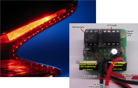
[Dave] spiced up his new 2012 Nissan Juke with a little tail-light amendment. You can see that outlining the rim of the light enclosure is a series of dots. This is an LED strip that he added to augment the brake lights. It’s glued in place, and features side emitting LEDs so that the light will be focused behind the car.

To control the strip he’s using an ATtiny85 microcontroller. It’s the chip on the right, and an optoisolator next to it protects it from the 12V vehicle power which drives the strip (via a MOSFET), and acts as a trigger when the brake pedal is pressed. He wrote a few effects into the firmware. When the lights are turned on, the strip fades up to 75% over about eight seconds. When the brake pedal is pressed they go to 100%. Check out the video after the break (it seems a little weird to us, as the video runs 18 seconds but the audio keeps going… YMMV).

We’ve seen a couple of tail light concepts that flash the brake lights when you stomp on the pedal. Unfortunately the Juke (and all other cars as far as we know) don’t have functionality built-in to sense when you’ve really given the brake a sudden jolt. It makes us wonder if this info could be gleaned from the CANbus? Continue reading “LED Strip And UC Add Some Flash To Your Tail Lights”

Making A Simple Addressable Array From LED Strips

led_array_from_led_strips

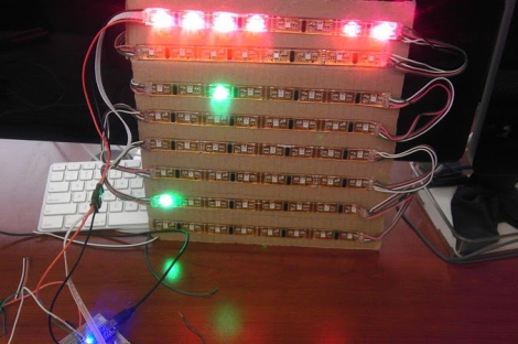
[Patrick] was prepping for some future projects he had in mind, for which he will need a simple 2D array of addressable LEDs. While it is certainly possible for him to build his own LED array and control hardware, he thought he would try out some off the shelf products to see if something might fit his needs.

He picked up a strip of addressable RGB LEDs from Adafruit, and while they worked very well, they were a bit too pricey for the amount of LEDs he knew he would need. He picked up a strip of similar LEDs without PWM capabilities built-in, and gave those a spin – they worked well enough, so he got to work building his LED array.

While LED strips might not jump right out as the best way to make an LED array, they can be easily cut and rearranged without any issue, provided you solder in a couple of wires to connect the disjointed strips. [Patrick] did just that, and wrote a small Arduino library that allows for easy control of the grid.

We’re not sure if he plans on scaling these arrays any larger than 8×8, but we are definitely interested to see what he has in store for them.

Check out a quick video of his LED array in action below.

Continue reading “Making A Simple Addressable Array From LED Strips”

Adding USB Control For Ikea RGB LED Strips

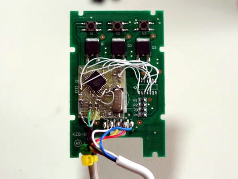
Here’s an altered PCB that gives USB control to an Ikea Dioder. This is a $50 product that comes with four strips each containing nine RGB LEDs. The stock controller has a color selection wheel and a couple of buttons. [Rikard Lindström] wanted to use it to match ambient light to the colors of his computer monitor — yes, it’s another ambilight clone.

Since he already had a bunch of AT90USB162 chips on hand he chose that route. These chips have native USB support (he’s using the LUFA package which is a popular choice), but no on-board ADC. That means no need for the potentiometer from the original controller because there’s no easy way to read its value. Removing it made plenty of room for his add-on PCB. He also depopulated the PIC microcontroller that originally drove the unit, soldering to the empty pads in order to connect is own board. The finished product fits back in the original case, with the addition of a USB cable as the only visible alteration. Now he can dial in colors using a program he wrote.

In case you’re wondering, it looks like this is a newer version of control circuitry when compared to the original Dioder hack we covered.