There is no company that has earned more goodwill from electronic tinkering hobbyists than Heathkit. For more than fifty years, Heathkit has been the measure all other electronic kit manufacturers have been compared to. Kits for everything – from televisions to radios to computer terminals – were all sold by Heathkit, and even now, nearly a quarter century since the last kit left the warehouse, there is still a desire for this manufacturer to rise like a phoenix from the ashes. Heathkit lives once more, and this time it might be for real.
In recent years, Heathkit has had a confusing, if not troubled business plan. The company started manufacturing its signature products – electronic kits of every kind – in 1947. Production of these kits ended in 1992, and the company went on for another few years manufacturing educational materials and lighting controls. In 2011, Heathkit said they were back in the kit business, before shutting down a year later.
In 2013, an official Heathkit Facebook page was launched, a reddit AMA was held, and a mysterious stranger in the Hackaday comments section found a geocache placed by someone at Heathkit in a Brooklyn park. Absolutely nothing happened in 2014, or at least no one cared enough to hire a PI, which brings us to today’s announcement: Heathkit lives yet again.
This morning, the president of Heathkit sent a message to the ‘Heathkit Insiders’ email group explaining the goings on and new happenings:
We’ve designed and developed a wide range of entirely new kit products. We authored the manuals for these kits, complete with the beautiful line art you rely on, preserving and respecting our iconic historic Heathkit style. We developed many new inventions and filed patents on them. We relocated Heathkit, and set up a factory, and a warehouse, and offices, in Santa Cruz, California, near Silicon Valley. We built the back office infrastructure, vendor and supply chain relationships, systems, procedures, operations methods, and well-thought-out corporate structure that a manufacturing company needs to support its customers, to allow us to scale instantly the day we resume major kit sales. All this effort enables us to introduce a fleet of new kits and helps ensure Heathkit can grow, prosper, and continue to bring you great new products for a very long time.
The new Heathkit shop features their newest product, the Explorer Jr. AM Radio Receiver kit, a small kit radio available for $150. It’s actually a rather interesting kit with a nice design and an air variable cap for tuning, just like radios from a century ago. Whether anyone will pay $150 for an AM receiver in this century is another question entirely. The 21st century rebirth of Heathkit doesn’t just mean kits; they’re making apps now, with the first release being a crystal design tool for Android.
Virtually everyone in this little corner of the Internet, from Adafruit to Sparkfun, to Make magazine to everyone with a 3D printer owes a debt to Heathkit. This is the company that first turned DIY electronics into a successful business. Heathkit was the first, and they deserve to be recognized as the pioneers of the field.
The Donner Party were pioneers, too; just because you’re breaking new ground doesn’t mean you’re successful. The Heathkit of the 90s shuttered its doors for a reason. The factors behind the 1992 closing – cheap stuff from China, and the fact that not many people want to build their own electronics – are still with us. Still, the market for DIY electronics may be big enough, and Heathkit’s back catalog may be diverse enough that I won’t have to write another ‘Heathkit dies yet again’ post in a year or so. We can only hope.


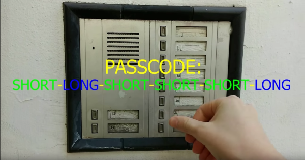
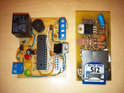 The design is pretty simple – an ATMega328P to snoop on the analog phone ringer in the apartment when the intercom call button is pushed, and a relay wired in parallel with the door switch to buzz him in. For added security, the microcontroller detects the pattern of button presses and prevents unwanted guests from accessing the lobby. Things got really fun when [Paweł] added a PCM audio module to play random audio clips through the intercom. As you can see in the video below, an incorrect code might result in a barking dog or a verbal put-down. But [Paweł] earns extra points for including the Super Mario Bros sound clip and for the mashup of the “Imperial March” with “The Girl from Ipanema”.

 Depending on whom you ask, the IoT seems to mean that whatever the thing is, it’s got a tiny computer inside with an Internet connection and is sending or receiving data autonomously. Put a computer in your toaster and