[Chris] has built a pocket calculator that emulates… a pocket calculator. Two pocket calculators, in fact. Inspired by [Ken Shirriff’s] incredible reverse engineering of the Sinclair scientific calculator, [Chris] decided to bring [Ken’s] Sinclair and TI Datamath 2500II simulators to the physical world.
Both of these classic 70’s calculators are based on the TMS0805 processor. The 0805 ran with 320 11-bit words of ROM and only three storage registers. Sinclair’s [Nigel Searle] performed the real hack by implementing scientific calculator operations on a chip designed to be a four function calculator.
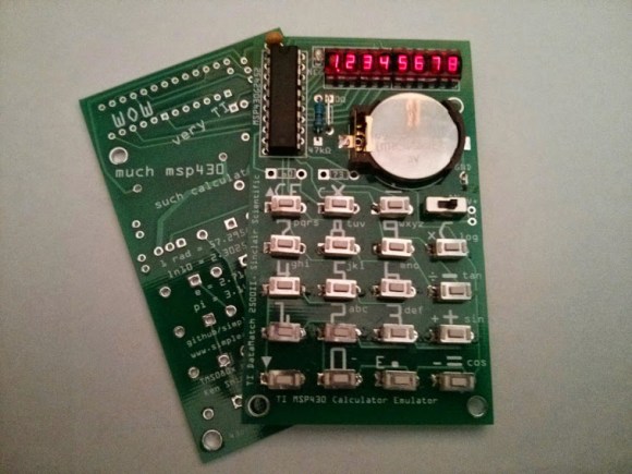
[Chris] decided to keep everything in the family by using a Texas Instruments msp430 microcontroller for emulation. He adapted [Ken’s] simulator code to run on a MSP430G2452. 256 bytes of RAM and a whopping 8KB of flash made things almost too easy.[Chris’] includes ROMs for both the TI and the Sinclair calculators. The TI Datamath ROM is default, but by holding the 7 key down during boot, the Sinclair ROM is loaded. The silk screen includes key icons for both calculators, as well as some Doge-inspired wisdom on the back.
All joking aside, these really are amazing little calculators. Children of the 60’s and 70’s will be taken back when they see the LEDs flash as the emulated TMS0805 performs algorithmic arithmetic. [Chris’] code is up on Github. While he hasn’t released gerbers yet, he does have images of his PCB layout on the 43oh.com forums.
Continue reading “Pocket Calculator Emulates Pocket Calculator”
 In the late 1800s, no one knew what light was. Everyone knew it behaved like a wave some of the time, but all waves need to travel through some propagation medium. This propagation medium was called the luminiferous aether and an attempt to detect and quantify this aether led to one of the coolest experimental setups of all time: the Michelson-Morely experiment. It was a huge interferometer mounted on a gigantic slab of marble floating in a pool of mercury. By rotating the interferometer, Michelson and Morely expected to see a small phase shift in the interferometer, both confirming the existence of a luminiferous aether and giving them how fast the Earth moved through this medium.
 We
We 
 I suppose I can take credit for introducing the super awesome [Fran Blanche] to Hackaday’s very own crotchety old man and Commodore refugee [Bil Herd]. I therefore take complete responsibility for
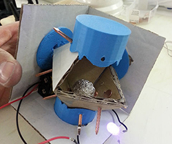 If you’re trying to detect the orientation of an object, sometimes you really don’t need a 6DOF gyro and accelerometer. Hell, if you only need to detect if an object is tilted, you can get a simple “ball in a tube” tilt sensor for pennies. [tamberg] liked this idea, but he required a tilt sensor that works in the X, Y, and Z axes. Expanding on the ‘ball in a tube’ construction of simple tilt sensors,


