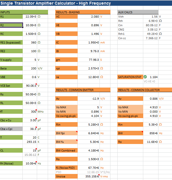
In our opinion, reverse engineering may be one of the best ways to tease your brain. [Andy] just did that by reverse engineering the Sony Ericsson Vivaz high resolution LCD (cached copy here). In his (very) nicely written article, [Andy] explains all the steps that led him to the result shown in the picture above. He started by finding the repair manual of the Vivaz, to discover that the display could be interfaced with 8080 type parallel signals. That meant that he could use a standard microcontroller without high speed buses to interface with it, in this case the STM32F4. Next in his adventure, [Andy] ordered the appropriate connector and took a more educated guess for the onboard microcontroller. A long Google search brought up the R61523 from Renesas. So he designed his breakout board, got it produced and a few hours later a nice picture was being shown on the LCD. He even took the time to compare the original display with the clone he found on the webs, and modified his graphics library to support this display.
HackPrinceton: Piano Stairs!
It was Hack.Princeton this weekend and [Bonnie] and [Erica] threw together this great interactive portable piano!
The setup is very simple using six LED flashlights, and six photoresistors. An Arduino Uno reads in the values from the photoresistors and parses them to a nearby Raspberry Pi which then creates the sounds. The system even automatically calibrates itself when turned on, adjusting to the ambient light conditions. They made the project for the Hackathon and after a short scare of having to move it to another staircase for the demo, they took home 2nd place in the hardware category!
Stick around after the break to see it in action — this would make a great school project to get kids interested in hacking!
Reverse Engineering The Z80’s 16-bit Increment/Decrement Circuit
Increment and decrement. They sound like simple functions. But even the simplest functions can get quite complex in a microprocessor design. Ken Shirriff has written up a great blog post about his reverse engineering of the Z80’s 16-bit increment/decrement circuit. The Zilog Z80 was one of the most popular microprocessors of the 70’s and 80’s. It was used in many classic computers such as the Osborne 1. These machines would often use the Z80 to run the popular CP/M operating system.
The increment/decrement circuit is responsible for updating the program counter register during normal (non branch) operations. The increment/decrement circuit also handles the stack pointer register during stack operations, as well as several other functions. One might wonder why a separate adder would be used when the microprocessor has a big ALU available to it. The answer is twofold. First the ALU is already in use handling user math operations. Secondly the increment/decrement circuit has to be fast. A generic ALU just won’t be fast enough.
One classic adding circuit is a Ripple Carry Adder. Ripple Carry Adders get the job done, but they are slow. Note slow is measured in nanoseconds here – there are no clocks involved in the circuit. The whole thing becomes a classic combinational logic optimization problem. Each layer of logic adds a gate delay to the circuit. As the carry has to ripple through all 16 bits, there are 16 gate delays before the final result is available at the outputs. Delays like these are what limits the maximum clock speed for a given circuit.
The Z80 uses some tricks in its increment/decrement circuit. The first is Carry-lookahead. A carry-lookahead circuit will calculate the carry values directly from the inputs. This reduces the gate delays significantly, but it requires more real estate on the die. A second trick is the carry-skip circuit. Carry-skip calculates the result for groups of bits rather than each bit individually. Again, it will reduce gate delays, at the cost of real estate. The actual Z80 implementation uses a mix of both circuits. Several other “helper” circuits are also used. Surprisingly the Z80 has specific logic just to check for 1 (0x0001) on the internal address bus. This circuit is used during memory move loops to inform other parts of the chip that a loop is about to complete.
Diagnose And Repair A Yaesu FT-7800 Ham Radio
[Alan Wolke] aka [w2aew] was challenged to repair a friends Yaesu FT-7800 ham radio. This radio operates on two ham bands, 2 m VHF and 70 cm UHF. The complaint was that the 2 m side was not working but the 70 cm was transmitting fine. Alan started by verifying the complaint using a Bird watt meter with a 50 watt slug and terminating the signal into a 50 W dummy load. [Allen’s] bird meter is the type that has an RF sampler that can be connected to an oscilloscope for added signal viewing and validation.
After verifying that the radio was not working as described, Alan starts by glancing over the circuit board to look for any obvious damage. He then walks us through a block diagram as well as a circuit diagram of the FT-7800 radio before stepping us through the troubleshooting and diagnostics of radio repair. Even when he realizes he might have found the problem he still steps us through the remainder of his diagnostics. The skills and knowledge that Alan shares is extremely valuable to anybody looking to repair radios.
Spoiler alert. At the end of the first video he determines that the pin diodes near the final VHF output were bad. In the second video he reveals that he could no longer source these bad components. Through some clever evaluation of a more current Yaesu radio, [Allen] was able to find suitable replacement components. Lesson two ends with some surface mount solder rework tips as well as testing that the repair was successful.
And just in case you don’t know what a pin diode is, or is used for, Alan shares a third video covering just what this component is and does in a radio. You can follow the jump to watch all three videos.
Continue reading “Diagnose And Repair A Yaesu FT-7800 Ham Radio”
Build Your Own Desoldering Station On The Cheap
[Sable Wolf] tipped us off to his DYI desoldering station for under $70. We know we have seen this conversion before, but it hasn’t been featured on Hack a Day. [Sable Wolf’s] hack is unique and has added features that make building, cleaning and the overall longevity sounder. However, some kind of sound deadening housing would have to be built around the pump as it seemed uncomfortably loud in the video.
Some Chinese made desoldering stations are getting quite cheap so maybe it’s not worth the effort unless you can salvage more components for the build. Thanks to [Sable Wolf’s] detailed blog you can browse through his BOM and scrounge up the majority of these items from your salvage bins. A cheap but reliable desoldering station would be an extremely handy tool to have on your bench.
This is much safer than desoldering with a candle or using fire as featured in the past, and is kind of a flip around on the SMD hot air pencil hack.
Follow long after the break to watch the video of the desoldering station in action.
Continue reading “Build Your Own Desoldering Station On The Cheap”
Hacking And Philosophy: Hacker Crackdown Part I
This week’s installment of Hacking & Philosophy hits the books with [Bruce Sterling’s] Hacker Crackdown. If you’re joining us for the first time, you should check out last week’s conversation over The Mentor’s “Hacker Manifesto.” Don’t stop with the article, though, or you’ll miss out on the best part!
The contributions from our community are phenomenal, and it’s worth the effort to work through the comments. There are even a few replies from [The Mentor] himself.
Unfortunately, I can’t feature all of the excellent responses for lack of room, but I will recommend a handful that I feel are uniquely important after the break. Onward for more!
Continue reading “Hacking And Philosophy: Hacker Crackdown Part I”
DIY CNC Rotary 4th Axis
Here’s a great CNC hack that adds a ton of functionality, a DIY rotary 4th axis!
[Jim] had started this project over a year ago when he originally ordered the gearhead off eBay, but like many good intentions, sometimes projects just get pushed to the back burner until necessity forces action. That necessity was entering our Trinket Contest, and he decided to finish it off just so he could put a HaD logo on a piece of PVC for us!
Unfortunately it took him a bit too long, and he only finished it last week — but luckily he had a fallback plan, and submitted his CNC Etch a Sketch project instead, which won him a Trinket anyway!
The 4th axis uses a 276oz-in stepper motor which is directly coupled to a Harmonic Drive Systems 11:1 planetary gearhead. It’s extremely accurate, has minimal backlash, and by using a 10 microstepping Gecko stepper drive, [Jim] is getting about 61 steps per degree of rotation. Not bad for a home-made setup!
Check out his blog for a great write up on the project, and stick around after the break to see the 4th axis in action.