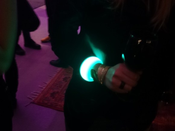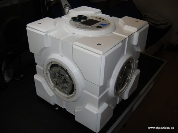
The Enrichment Center likely disapproves of the SoundCube: a portal music box in the form of a Portal Companion Cube. [Andreas] finished this project a couple of years ago, but we’re glad he’s finally had time to give a rundown on the details at his blog.
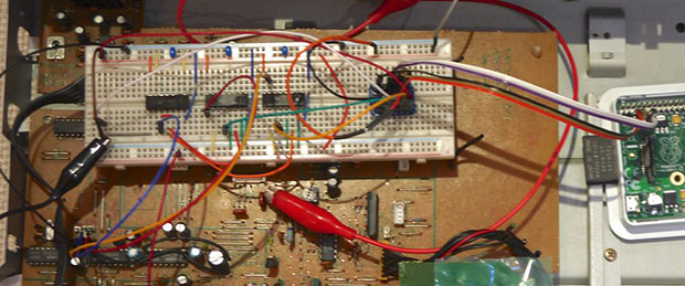
The build is primarily a modified speaker box cube—constructed out of what appears to be MDF—with four Alpine SXE-1725S speakers placed at the center of the middle faces. The faces were routed out to resembled the Companion Cube, while the electronics mount and the speaker grills were 3d printed. Inside is a homemade amplifier built around an Arduino Mega, with a TDA7560 quad bridge amplifier, a TDA7318 audio processor, a Belkin bluetooth receiver, and a 3.5″ touchscreen for volume control and for input selections.
Two 12v 7.2Ah lead-acid batteries keep the cube functional for an entire weekend of partying, but probably add a few pounds to the already hefty MDF construction. Check out [Andreas’s] blog for more pictures and his GitHub for all the necessary code.