Super Pixel Bros Now With Manufactured PCB And Rewritten Software

[Retro Brad] has come a long way with his 8×8 gaming device which he calls Super Pixel Bros. The newest rendition has a fab house PCB and freshly rewritten code. The game is still played on an 8×8 LED matrix, but it looks like he’s sourced a version with square pixels, which is a nice touch since he was inspired by the block-based Super Mario games. Also new in this version is the character LCD screen which displays score, level, and life information. But it’s not just the shiny new hardware that’s different, he’s rewritten the software in Swordfish Basic to run on the PIC 18F4550. The new code allowed him to tweak how levels are loaded and stored. He’s even written a level editor and has finished 20 levels thus far.

The demo after the break does a great job of showing off the hardware and the game play. He’s added a lot, including enemies, the ability to shoot fire, and of course the common moves of jumping and breaking blocks is all there. He mentioned that the fab house he used is selling boards for around $5 and he’s looking into the possibility of getting a kit service up and running.

His progress since we last checked in on the project is quite impressive.

Continue reading “Super Pixel Bros Now With Manufactured PCB And Rewritten Software”
[Dino’s] JFET Guitar Preamp With Piezo Pickup

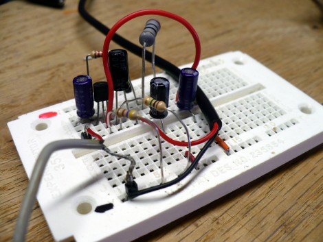
This week, with a little help from a Roomba, [Dino] built a guitar pickup and preamp that sounds marvelous. A pickup takes vibrations from the guitar and turns them into an electrical signal which can then be amplified and broadcast. He grabbed a long-dead Roomba which has slowly but surely been donating its organs for his weekly projects. After plucking out a piezo element he grabbed a bag of Junction gate Field-Effect Transistors (JFET) and built a preamp circuit around one of them.

JFETs operate in much the same way as MOSFETs (which we took a look at last week). [Dino’s] design adds a few resistors and capacitors to tune the gain and decouple the circuit from the input and power rails. He epoxied the piezo element inside the guitar and connected leads between it and a jack mounted in the body. As always, he does an excellent job of explaining the concepts behind the design and outlining the build techniques that he used. We’ve embedded his video after the break.

Continue reading “[Dino’s] JFET Guitar Preamp With Piezo Pickup”

Inkjet Print Head Driver Shield

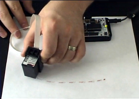
[Nicolas C Lewis] is churning out inkjet print head shield kits for Arduino. If you’ve always wanted to label or brand objects as part of a project this greatly simplifies the process. Using his all through-hole design, an Arduino can print at 96 dpi. At first we had trouble figuring out what we could use this concept for, but [Nicolas] has the answer. In is FAQ he links to a couple of his own flat-bed inkjet printer builds based on earlier prototypes, but he also links to other projects using the same concepts like the Nickel-O-Matic, or the ping-pong ball printer (we’ve embedded video of that one after the break).

The shield only requires five connections with a microcontroller. We love the jumper-based connection system that [Nicolas] chose which lets you use several print heads at once by selecting different drive pins. The project is still in the funding stage but is already over funded. Schematic and code will be posted as soon as the first production run is complete.

Continue reading “Inkjet Print Head Driver Shield”

PCB Drill From R/C Car Parts

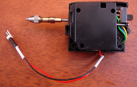
[Sid] makes a few PCBs a month and the hardest part of his fabrication process is always drilling the through-holes. He has a PCB hand drill that usually results in a sore index finger. After a few unsuccessful attempts of using a full-size electric drill and not wanting to invest in a commercial solution, [Sid] made a PCB drill from a broken R/C car.

The toy car was donated by [Sid]’s 4-year-old after a terrible crash. [Sid] took the gearbox from the car and added a small circuit to control the direction of the drill. After attaching the drill chuck to the former R/C car axle and adding the power leads to a 5 Volt adapter, a PCB drill press was born.

Most of the parts for this build were salvaged from the toy car’s radio control circuit. Except for the chuck from [Sid]’s hand drill and a few switches, everything on this build was pulled from a broken remote control car. While the build is a lot simpler than this semi-automatic PCB drill, [Sid]’s drill seems to work well. Check out the demo video after the break.

Continue reading “PCB Drill From R/C Car Parts”

A Simple Fix To Resurrect Your Broken Iclicker

simple_iclicker_battery_fix

If you are currently attending college, the odds are that you are familiar with iclicker classroom remotes. If you have one of these, you might also be aware that they tend to be flaky at times, particularly when it comes to powering on. [Todd] received a few “broken” iclickers lately and has found an easy to fix design issue that might possibly save yours (and others) from the trash heap.

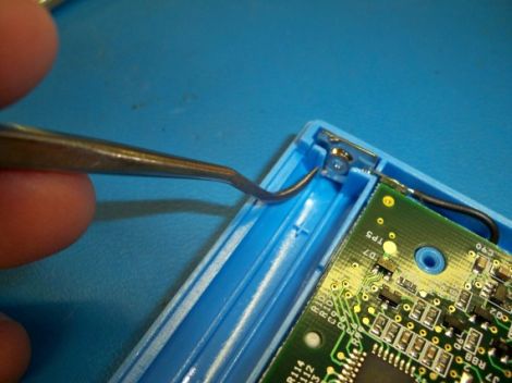
When he started pulling the units apart to diagnose them, he noticed that something with the battery contacts was not quite right. They are held in place by the device’s plastic shell which is pretty common, however in the iclicker, the portion of the plastic case that holds the positive battery contact is too big, preventing some batteries from making a complete circuit.

Now you might be thinking to yourself that AA batteries are all the same, but they are not necessarily created equal. Through a small bit of testing, [Todd] found that many different batteries experienced intermittent connectivity issues depending on the height of the positive terminal, and that due to their design, Duracell batteries flat out didn’t work. With the careful removal of a portion of the plastic surrounding the positive contact, [Todd] was able to fix each of his “broken” remotes.

He hopes that this information helps some people resurrect their non-functioning units, because a few minutes work sure beats buying another $30 iclicker.

geochron_world_clock_clone

World Clock Simulates Night And Day

[Justin] always wanted a GeoChron clock, but since they run in the range of several thousand dollars apiece, he was pretty certain he would never have the chance to own one. Undaunted, he figured out a way to build a small version of the clock for himself, and he wrote in to share how it was done.

He first purchased a Wise Clock 3 from FlorinC, but he definitely wasn’t going to use the clock as it was originally intended. Rather than display the time in numbers, he pulled the Wise Clock apart and sandwiched a vellum printout of a world map in between the front face plates. A tweaked firmware image allows him to simulate day and night using the Wise Clock’s LED array. He also programmed the clock to take into account seasonal light patterns, as you can see in the video embedded below.

We think this is a great idea, and though we would probably use plain white LEDs if we built one, the RGB LEDs in the Wise Clock certainly provide a neat effect.

Continue reading “World Clock Simulates Night And Day”

Announcing Our Next Theme: ATtiny Hacks

ATtiny Hacks Theme Banner

It is time once again to announce a new theme. This time around, we have chosen to highlight projects built around the ATtiny series of processors. These are 6 to 32 pin AVR processors that run up to 16 MHz and have anywhere from 512 Bytes of flash with 32 Bytes of RAM to 16K of Flash with 512 bytes of RAM. We’re guessing that this will be a pretty popular theme since so many people are using Atmel processors these days. If you have a project that you would like to see on Hackaday that is using an ATtiny processor, please hit us up on our tip line. If we like it, we may we choose to feature it in one of our daily themed hacks.

To kick off this theme, here is a nice write up about a stepper motor driver based around the ATtiny13. This project reads the analog value on pin B4 and adjusts the speed of the stepper motor. It is well documented and includes source code.