The five picos on two breadboards and the results of image convolution.

PentaPico: A Pi Pico Cluster For Image Convolution

Here’s something fun. Our hacker [Willow Cunningham] has sent us a copy of their homework. This is their final project for the “ECE 574: Cluster Computing” course at the University of Maine, Orono.

It was enjoyable going through the process of having a good look at everything in this project. The project is a “cluster” of 5x Raspberry Pi Pico microcontrollers — with one head node as the leader and four compute nodes that work on tasks. The software for both types of node is written in C. The head node is connected to a workstation via USB 1.1 allowing the system to be controlled with a Python script.

The cluster is configured to process an embarrassingly parallel image convolution. The input image is copied into the head node via USB which then divvies it up and distributes it to n compute nodes via I2C, one node at a time. Results are given for n = {1,2,4} compute nodes.

It turns out that the work of distributing the data dwarfs the compute by three orders of magnitude. The result is that the whole system gets slower the more nodes we add. But we’re not going to hold that against anyone. This was a fascinating investigation and we were impressed by [Willow]’s technical chops. This was a complicated project with diverse hardware and software challenges and they’ve done a great job making it all work and in the best scientific tradition.

It was fun reading their journal in which they chronicled their progress and frustrations during the project. Their final report in IEEE format was created using LaTeX and Overleaf, at only six pages it is an easy and interesting read.

For anyone interested in cluster tech be sure to check out the 256-core RISC-V megacluster and a RISC-V supercluster for very low cost.

A white control box is shown in the foreground. The box has an LCD display, eight button, and two barbed fittings for flexible tubing.

Using Pitot Tubes For More Than Aircraft

When we hear the words “pitot tube,” we tend to think more of airplanes than of air ducts, but [Franci Kopač]’s guide to pitot tubes for makers shows that they can be a remarkably versatile tool for measuring air speed, even in domestic settings.

A pitot tube is a tube which faces into an air flow, with one hole at the front of the tube, and one on the side. It’s then possible to determine the air speed by measuring the pressure difference between the side opening and the end facing into the wind. At speeds, temperatures, and altitudes that a hacker’s likely to encounter (i.e. not on an airplane), the pressure difference is pretty small, and it’s only since the advent of MEMS pressure sensors that pitot tubes became practical for amateurs.

[Franci]’s design is based on a Sensiron SDP differential pressure sensor, a 3D-printed pitot tube structure, some tubing, and the microcontroller of your choice. It’s important to position the tube well, so that it doesn’t experience airflow disturbances from other structures and faces straight into the air flow. Besides good positioning, the airspeed calculation requires you to know the air temperature and absolute pressure.

[Franci] also describes a more exotic averaging pitot tube, a fairly simple variation which measures air speed in cavities more accurately. He notes that this provides a more inexpensive way of measuring air flow in ducts than air conditioning flow sensors, while being more resilient than propeller-based solutions – he himself used pitot tubes to balance air flow in his home’s ventilation. All of the necessary CAD files and Arduino code are available on his GitHub repository.

If you’re looking for a more conventional duct flow meter, we’ve covered one before. We’ve even seen a teardown of a pitot tube sensor system from a military drone.

Two rings of magnets are shown encasing a circular channel in a white plastic piece. The channel is filled with liquid metal, and a loop of wire is about to be lowered into the metal.

Magnetohydrodynamic Motors To Spin Satellites

Almost all satellites have some kind of thrusters aboard, but they tend to use them as little as possible to conserve chemical fuel. Reaction wheels are one way to make orientation adjustments without running the thrusters, and [Zachary Tong]’s liquid metal reaction wheel greatly simplifies the conventional design.

Reaction wheels are basically flywheels. When a spacecraft spins one, conservation of angular momentum means that the wheel applies an equal and opposite torque to the spacecraft, letting the spacecraft orient itself. The liquid-metal reaction wheel uses this same principle, but uses a loop of liquid metal instead of a wheel, and uses a magnetohydrodynamic drive to propel the metal around the loop.

[Zach] built two reaction wheels using Galinstan as their liquid metal, which avoided the toxicity of a more obvious liquid metal. Unfortunately, the oxide skin that Galinstan forms did make it harder to visualize the metal’s motion. He managed to get some good video, but a clearer test was their ability to produce torque. Both iterations produced a noticeable response when hung from a string and activated, and achieved somewhat better results when mounted on a 3D-printed air bearing.

Currently, efficiency is the main limitation of [Zach]’s motors: he estimates that the second model produced 6.2 milli-newton meters of torque, but at the cost of drawing 22 watts. The liquid metal is highly conductive, so the magnetohydrodynamic drive takes high current at low voltage, which is inconvenient for a spacecraft to supply. Nevertheless, considering how hard it is to create reliable, long-lasting reaction wheels the conventional way, the greatly improved resilience of liquid-metal reaction wheels might eventually be worthwhile.

If you’re curious for a deeper look at magnetohydrodynamic drives, we’ve covered them before. We’ve also seen [Zach]’s earlier experiments with Galinstan.

Continue reading “Magnetohydrodynamic Motors To Spin Satellites”

Escaping US Tech Giants Leads European YouTuber To Open Source

The video (embedded below) by [TechAltar] is titled “1 Month without US tech giants“, but it could have been titled “1 Month with Open Source Tools” — because, as it turns out, once you get out of the ecosystem set up by the US tech giants, you’re into the world of open source software (OSS) whether you want to be or not.

From a (German-made) Tuxedo laptop running their own Linux distro to a Fairphone with e/OS (which is French), an open version of Android, [TechAlter] is very keen to point out whenever Europeans are involved, which is how we learned that KDE has a physical headquarters, and that it’s in Berlin. Who knew?

He also gives his experiences with NextCloud (also German), can be used as an OSS alternative Google Workspaces that we’ve written about before, but then admits that he was the sole user on his instance. To which one must question: if you’re the sole user, why do you need a cloud-based collaborative environment? To try it out before getting collaborators involved, presumably.

Regardless what you think of the politics motivating this video, it’s great to see open source getting greater traction. While [TechAltar] was looking for European alternatives, part of the glory of open source is that it doesn’t matter where you’re from, you can still contribute. (Unless you’re Russian.) Have you found yourself using more open source software (or hardware) of late? Do you think the current political climate could lead to a broadening of its reach? Is this the year of the linux desktop? Let us know what you think in the comments. Continue reading “Escaping US Tech Giants Leads European YouTuber To Open Source”

Hackaday Podcast Episode 321: Learn You Some 3DP, Let The Wookie Win, Or Design A Thinkpad Motherboard Anew

Join Hackaday Editors Elliot Williams and Tom Nardi as they take a whirlwind tour of the best and brightest hacks of the last week. This episode starts off with an update about that Soviet Venus lander that’s been buzzing the planet, then moves on to best practices for designing 3D printed parts, giving Chrome OS devices a new lease on life, and a unique display technology that brings a Star Wars prop to life.

You’ll also hear about designing new motherboards for beloved old computers, why you might want to put your calipers on a flatbed scanner, and a NASA science satellite that’s putting in double duty as a wartime reporter. Finally, they’ll cover the interesting physics of meteor burst communications, and the latest developments in the ongoing libogc license kerfuffle.

Check out the links below if you want to follow along, and as always, tell us what you think about this episode in the comments!

Download in DRM-free MP3.

Continue reading “Hackaday Podcast Episode 321: Learn You Some 3DP, Let The Wookie Win, Or Design A Thinkpad Motherboard Anew”

Simulating High-Side Bootstrap Circuits With LTSpice

LTSpice is a tool that every electronics nerd should have at least a basic knowledge of. Those of us who work professionally in the analog and power worlds rely heavily on the validity of our simulations. It’s one of the basic skills taught at college, and essential to truly understand how a circuit behaves. [Mano] has quite a collection of videos about the tool, and here is a great video explanation of how a bootstrap circuit works, enabling a high-side driver to work in the context of driving a simple buck converter. However, before understanding what a bootstrap is, we need to talk a little theory.

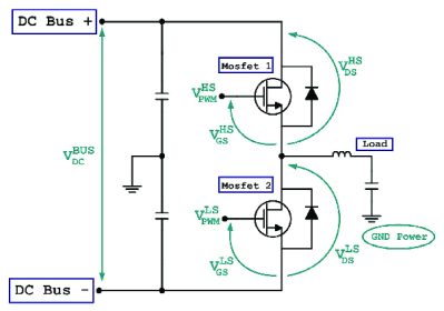
Bootstrap circuits are very common when NMOS (or NPN) devices are used on the high side of a switching circuit, such as a half-bridge (and by extension, a full bridge) used to drive a motor or pump current into a power supply.

A simple half-bridge driving illustrates the high-side NMOS driving problem.

From a simplistic viewpoint, due to the apparent symmetry, you’d want to have an NMOS device at the bottom and expect a PMOS device to be at the top. However, PMOS and PNP devices are weaker, rarer and more expensive than NMOS, which is all down to the device physics; simply put, the hole mobility in silicon and most other semiconductors is much lower than the electron mobility, which results in much less current. Hence, NMOS and NPN are predominant in power circuits.

As some will be aware, to drive a high-side switching transistor, such as an NPN bipolar or an NMOS device, the source end will not be at ground, but will be tied to the switching node, which for a power supply is the output voltage. You need a way to drive the gate voltage in excess of the source or emitter end by at least the threshold voltage. This is necessary to get the device to fully turn on, to give the lowest resistance, and to cause the least power dissipation. But how do you get from the logic-level PWM control waveform to what the gate needs to switch correctly?

The answer is to use a so-called bootstrap capacitor. The idea is simple enough: during one half of the driving waveform, the capacitor is charged to some fixed voltage with respect to ground, since one end of the capacitor will be grounded periodically. On the other half cycle, the previously grounded end, jumps up to the output voltage (the source end of the high side transistor) which boosts the other side of the capacitor in excess of the source (because it got charged already) providing a temporary high-voltage floating supply than can be used to drive the high-side gate, and reliably switch on the transistor. [Mano] explains it much better in a practical scenario in the video below, but now you get the why and how of the technique.

We see videos about LTSpice quite a bit, like this excellent YouTube resource by [FesZ] for starters.

Continue reading “Simulating High-Side Bootstrap Circuits With LTSpice”

A Single-Pixel Camera Without Moving Parts Using Compressed Sensing

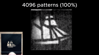
One of the reconstructed images, using all 4,096 matrix patterns as input, next to the original object. (Credit: okooptics, Jon Bumstead)

There’s a strange allure to single-pixel cameras due to the simultaneous simplicity and yet fascinating features that they can offer, such as no set resolution limit. That said, the typical implementations that use some kind of scanning (MEMS) mirror or similar approach suffer from various issues even when you’re photographing a perfectly stationary and static scene due to their complex mechanical nature. Yet there’s a way around this, involving a LED matrix and a single photoresistor, as covered by [Jon Bumstead] in an article with accompanying video.

As he points out, this isn’t a new concept, with research papers cited that go back many years. At the core lies the signal processing technique called compressed sensing, which is incidentally also used with computed tomography (CT) and magnetic resonance imaging (MRI) scanners. Compressed sensing enables the reconstruction of a signal from a series of samples, by using existing knowledge of the signal.

In the case of this single-pixel camera, the known information is the illumination, which is a Hadamard matrix pattern displayed on the 64 x 64 pixel LED matrix, ergo 4,096 possible patterns. A total of 4,096 samples are thus recorded, which are subsequently processed with a Matlab script. As pointed out, even 50% of the maximum possible matrices can suffice here, with appropriately chosen patterns.

While not an incredibly fast method, it is fully solid-state, can be adapted to use other wavelengths, and with some tweaking of the used components probably could cut down the sampling time required.

Continue reading “A Single-Pixel Camera Without Moving Parts Using Compressed Sensing”