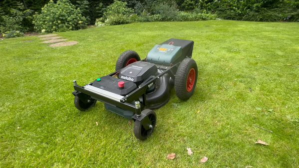
Long-tail pair waves

Current Mirrors Tame Common Mode Noise

If you’re the sort who finds beauty in symmetry – and I’m not talking about your latest PCB layout – then you’ll appreciate this clever take on the long-tailed pair. [Kevin]’s video on this topic explores boosting common mode rejection by swapping out the old-school tail resistor for a current mirror. Yes, the humble current mirror – long underestimated in DIY analog circles – steps up here, giving his differential amplifier a much-needed backbone.

So why does this matter? Well, in Kevin’s bench tests, this hack more than doubles the common mode rejection, leaping from a decent 35 dB to a noise-crushing 93 dB. That’s not just tweaking for tweaking’s sake; that’s taking a breadboard standard and making it ready for sensitive, low-level signal work. Instead of wrestling with mismatched transistors or praying to the gods of temperature stability, he opts for a practical approach. A couple of matched NPNs, a pair of emitter resistors, and a back-of-the-envelope resistor calculation – and boom, clean differential gain without the common mode muck.

If you want the nitty-gritty details, schematics of the demo circuits are on his project GitHub. Kevin’s explanation is equal parts history lesson and practical engineering, and it’s worth the watch. Keep tinkering, and do share your thoughts on this.

Continue reading “Current Mirrors Tame Common Mode Noise”

Turning Down The Noise On SMPS

On paper, electricity behaves in easy-to-understand, predictable ways. That’s mostly because the wires on the page have zero resistance and the switching times are actually zero, whereas in real life neither of these things are true. That’s what makes things like switch-mode power supplies (SMPS) difficult to build and troubleshoot. Switching inductors and capacitors tens or hundreds of thousands of times a second (or more) causes some these difficulties to arise when these devices are built in the real world. [FesZ Electronis] takes a deep dive into some of the reasons these difficulties come up in this video.

The first piece of electronics that can generate noise in an SMPS are the rectifier diodes. These have a certain amount of non-ideal capacitance as well as which causes a phenomenon called reverse current, but this can be managed by proper component choice to somewhat to limit noise.

The other major piece of silicon in power supplies like this that drives noise are the switching transistors. Since the noise is generally caused by the switching itself, there is a lot that can be done here to help limit it. One thing is to slow down the amount of time it takes to transition between states, limiting the transients that form as a result of making and breaking connections rapidly. The other, similar to selecting diodes, is to select transistors that have properties (specifically relating to inherent capacitances) that will limit noise generation in applications like this.

Of course there is a lot more information as well as charts and graphs in [FesZ]’s video. He’s become well-known for deep dives into practical electrical engineering topics like these for a while now. We especially like his videos about impedance matching as well as a more recent video where he models a photovoltaic solar panel in SPICE.

Continue reading “Turning Down The Noise On SMPS”

Recreating A Braun Classic With 3D Printing

Braun was once a mighty pillar of industrial design; a true titan of the mid-century era. Many of the company’s finest works have been forgotten outside of coffee table books and vintage shops. [Distracted by Design] wanted to bring one of the classics back to life—the Braun HL70 desk fan.

The original was quite a neat little device. It made the most of simple round shapes and was able to direct a small but refreshing stream of air across one’s desk on a warm day. In reality, it was probably bought as much for its sleek aesthetics as for its actual cooling ability.

Obviously, you can’t just buy one anymore, so [Distracted by Design] turned to 3D printing to make their own. The core of the build was a mains-powered motor yanked out of a relatively conventional desk fan. However, it was assembled into a far more attractive enclosure that was inspired by the Braun HL70, rather than being a direct copy. We get a look at both the design process and the final assembly, and the results are quite nice. It feels like a 2025 take on the original in a very positive sense.

Files are available on Printables for the curious. It’s not the first time we’ve contemplated fancy fans and their designs. Video after the break.

Continue reading “Recreating A Braun Classic With 3D Printing”

Repairing A Legendary Elka Synthex Analog Synthesizer

Handy diagnostic LEDs on the side of the tone generator boards. (Credit: Mend it Mark, YouTube)

Somehow, an Elka Synthex analog synthesizer made it onto [Mend it Mark]’s repair bench recently. It had a couple of dud buttons, and some keys produced the wrong tone. Remember, this is an analog synthesizer from the 1980s, so we’re talking basic 74LS chips and kin. Fortunately, Elka helped him with the complete repair manual, including schematics.

As usual, [Mark] starts by diagnosing the faults, using the schematics to mark the parts of the circuitry to focus on. Then, the synth’s bonnet is popped open to reveal its absolutely gobsmackingly delightful inner workings, with neatly modular PCBs attached to a central backplane. The entire unit is controlled by a 6502 MPU, with basic counter ICs handling tone generation, controlled by top panel settings.

The Elka Synthex is a polyphonic analog synthesizer produced from 1981 to 1985 and used by famous artists, including Jean-Michel Jarre. Due to its modular nature, [Mark] was quickly able to hunt down the few defective 74LS chips and replace them before testing the instrument by playing some synth tunes from Jean-Michel Jarre’s Oxygène album, as is proper with a 1980s synthesizer.

Looking for something simpler? Or, perhaps, you want something not quite that simple.

Continue reading “Repairing A Legendary Elka Synthex Analog Synthesizer”

Ask Hackaday: What Would You Do With The World’s Smallest Microcontroller?

It’s generally pretty easy to spot a microcontroller on a PCB. There are clues aplenty: the more-or-less central location, the nearby crystal oscillator, the maze of supporting passives, and perhaps even an obvious flash chip lurking about. The dead giveaway, though, is all those traces leading to the chip, betraying its primacy in the circuit. As all roads lead to Rome, so it often is with microcontrollers.

It looks like that may be about to change, though, based on Texas Instruments’ recent announcement of a line of incredibly small Arm-based microcontrollers. The video below shows off just how small the MSPM0 line can be, ranging from a relatively gigantic TSSOP-20 case down to an eight-pin BGA package that measures only 1.6 mm by 0.86 mm. That’s essentially the size of an 0603 SMD resistor, a tiny footprint for a 24-MHz Cortex M0+ MCU with 16-kB of flash, 1-kB of SRAM, and a 12-bit ADC. The larger packages obviously have more GPIO brought out to pins, but even the eight-pin versions support six IO lines.

Of course, it’s hard not to write about a specific product without sounding like you’re shilling for the company, but being first to market with an MCU in this size range is certainly newsworthy. We’re sure other manufacturers will follow suit soon enough, but for now, we want to know how you would go about using a microcontroller the size of a resistor. The promo video hints at TI’s target market for these or compact wearables by showing them used in earbuds, but we suspect the Hackaday community will come up with all sorts of creative and fun ways to put these to use — shoutout to [mitxela], whose habit of building impossibly small electronic jewelry might be a good use case for something like this.

There may even be some nefarious use cases for a microcontroller this small. We were skeptical of the story about “spy chips” on PC motherboards, but a microcontroller that can pass for an SMD resistor might change that equation a bit. There’s also the concept of “Oreo construction” that these chips might make a lot easier. A board with a microcontroller embedded within it could be a real security risk, but on the other hand, it could make for some very interesting applications.

What’s your take on this? Can you think of applications where something this small is enabling? Or are microcontrollers that are likely to join the dust motes at the back of your bench after a poorly timed sneeze a bridge too far? Sound off in the comments below.

Continue reading “Ask Hackaday: What Would You Do With The World’s Smallest Microcontroller?”

Build Your Own Air Mouse, Okay?

Are you using a desk mouse like some kind of… normal computer user? Why, beg the heavens? For you could be using an air mouse, of your very own creation! [Misfit Maker] shows the way. Check out what he made in the video below.

An air mouse is a mouse you use in the air—which creates at least one major challenge. Since you’re not sliding along a surface, you can’t track the motion by mechanical friction like a ball mouse or by imaging as in an optical mouse. Instead, this build relies on a gyroscope sensor to track motion and translate that into pointer commands. The build relies on an ESP32-C3 as the microcontroller at the heart of things. It communicates with an MPU6050 gyroscope and accelerometer to track motion in space. It then communicates as a human interface device over Bluetooth, so you can use it with lots of different devices. The mouse buttons—plus media control buttons—are all capacitive touch-sensitive, thanks to an MPR121 touch sensor module.

There’s something neat about building your own tools to interface with the machines, almost like it helps meld the system to your whims. We see a lot of innovative mouse and HID projects around these parts.

Continue reading “Build Your Own Air Mouse, Okay?”

Relativity Space Changes Course On Path To Orbit

In 2015, Tim Ellis and Jordan Noone founded Relativity Space around an ambitious goal: to be the first company to put a 3D printed rocket into orbit. While additive manufacturing was already becoming an increasingly important tool in the aerospace industry, the duo believed it could be pushed further than anyone had yet realized.

Rather than assembling a rocket out of smaller printed parts, they imagined the entire rocket being produced on a huge printer. Once the methodology was perfected, they believed rockets could be printed faster and cheaper than they could be traditionally assembled. What’s more, in the far future, Relativity might even be able to produce rockets off-world in fully automated factories. It was a bold idea, to be sure. But then, landing rockets on a barge in the middle of the ocean once seemed pretty far fetched as well.

An early printed propellant tank.

Of course, printing something the size of an orbital rocket requires an exceptionally large 3D printer, so Relativity Space had to built one. It wasn’t long before the company had gotten to the point where they had successfully tested their printed rocket engine, and were scaling up their processes to print the vehicle’s propellant tanks. In 2018 Bryce Salmi, then an avionics hardware engineer at Relatively Space, gave a talk at Hackaday Supercon detailing the rapid progress the company had made so far.

Just a few years later, in March of 2023, the Relativity’s first completed rocket sat fueled and ready to fly on the launch pad. The Terran 1 rocket wasn’t the entirely printed vehicle that Ellis and Noone had imagined, but with approximately 85% of the booster’s mass being made up of printed parts, it was as close as anyone had ever gotten before.

The launch of Terran 1 was a huge milestone for the company, and even though a problem in the second stage engine prevented the rocket from reaching orbit, the flight proved to critics that a 3D printed rocket could fly and that their manufacturing techniques were sound. Almost immediately, Relativity Space announced they would begin work on a larger and more powerful successor to the Terran 1 which would be more competitive to SpaceX’s Falcon 9.

Now, after an administrative shakeup that saw Tim Ellis replaced as CEO, the company has released a nearly 45 minute long video detailing their plans for the next Terran rocket — and explaining why they won’t be 3D printing it.

Continue reading “Relativity Space Changes Course On Path To Orbit”