DIY Rubber Ducky Is As Cheap As Its Namesake

The “Rubber Ducky” by Hak5 is a very powerful tool that lets the user perform rapid keystroke injection attacks, which is basically a fancy way of saying the device can type fast. Capable of entering text at over 1000 WPM, Mavis Beacon’s got nothing on this $45 gadget. Within just a few seconds of plugging it in, a properly programmed script can do all sorts of damage. Just think of all the havoc that can be caused by an attacker typing in commands on the local machine, and now image they are also the Flash.

But unless you’re a professional pentester, $45 might be a bit more than you’re looking to spend. Luckily for the budget conscious hackers out there, [Tomas C] has posted a guide on using open source software to create a DIY version of Hak5’s tool for $3 a pop. At that cost, you don’t even have to bother recovering the things when you deploy them; just hold on tight to your balaclava and make a run for it.

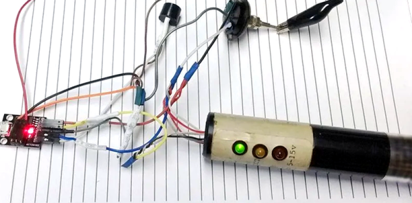
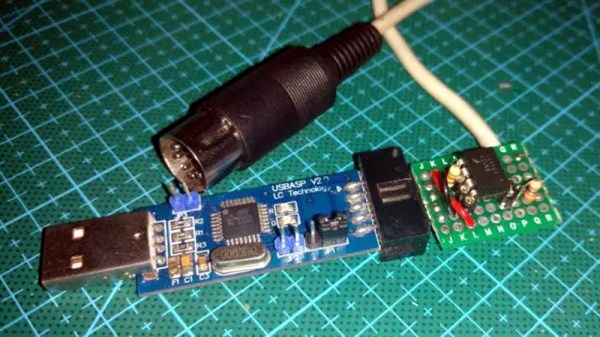
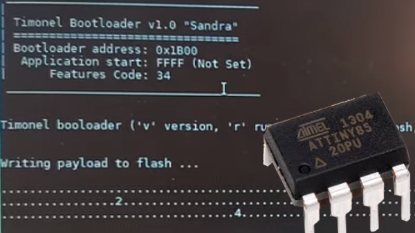
The hardware side of this hack is the Attiny85-based Digispark, clones of which can be had for as low as $1.50 USD depending on how long your willing to wait on the shipping from China. Even the official ones are only $8, though as of the time of this writing are not currently available. Encapsulating the thing in black shrink tubing prevents it from shorting out, and as an added bonus, gives it that legit hacker look. Of course, it wouldn’t be much of a hack if you could just buy one of these little guys and install the Rubber Ducky firmware on it.

In an effort to make it easier to use, the official Rubber Ducky runs scripts written in a BASIC-like scripting language. [Tomas C] used a tool called duck2spark by [Marcus Mengs], which lets you take a Rubber Ducky script (which have been released by Hak5 as open source) and compile it into a binary for flashing to the Digispark.

Not quite as convenient as just copying the script to the original Ducky’s microSD card, but what do you want for less than 1/10th the original’s price? Like we’ve seen in previous DIY builds inspired by Hak5 products, the trade-off is often cost for ease of use.

[Thanks to Javier for the tip.]

Less Is More: A Micromatrix Display In A Square Inch

In your living room, the big display is what you want. But in an embedded project, often less is more. We think [bobricius] will agree since he submitted a tiny 4×5 LED display into our square inch challenge. The board features an ATtiny CPU and twenty SMD LEDs in a nice grid. You can see them in action, scrolling to some disco music in the video below.

There is plenty of room left in the CPU for bigger text strings — the flash memory is just over 10% full. A little side-mounted header makes it easy to program the chip if you want to change anything.

Continue reading “Less Is More: A Micromatrix Display In A Square Inch”

Measure Resistance The Colourful Way

One of the first things anyone with an interest in electronics learns is the resistor colour code. The colour of the first band reveals the first figure, the second the subsequent figure, and the third a power-of-ten multiplier. At first you learn these colours, but eventually you just recognise the values through familiarity. You don’t have to think about multipliers when you see orange-orange-red, you just know that it’s a 3K3 resistor.

[Plusea] has come up with an entertaining interface for an ohmmeter, which instead of displaying the resistance on an LCD or a meter shows it as the colours of the code, via a set of addressable LEDs. The work is done by an ATtiny85 microcontroller, and the whole thing is mounted on a flexible PCB (fabrication of which is itself interesting, placing cut copper traces on a sheet of kapton and covering with a second kapton layer cut to be the solder mask). There is even a clever integration of a CR2032 battery holder from the PCB itself, though they admit that it could be made more compact with the use of SMD components instead of through-hole.

The write-up and associated photo album tells us a lot about the project, but is missing a crucial detail: a shot of it working. We’ll give them the benefit of the doubt on that front though, because we like the idea and its execution.

Strangely, this isn’t the first ohmmeter to use the resistor colour code in this way, we’ve previously brought you one featuring a light-up giant resistor.

Custom ATTiny85 Board Powers Kids’ Light Show

We’ve often said that kids with hackers and makers for parents must be some of the luckiest kids in the world. While all the other children have to settle for some mass produced drivel from Toys“R”Us Amazon, they’ve got some of the most thoughtfully engineered and built toys and gadgets on the planet. After all, there’s no way any hacker worth their salt is going to give anything less than 110% for their own child.

A case in point is this RGB star nightlight that [Unexpected Maker] built for his children. The star itself is simple enough, just a basic shape printed in transparent PLA on his Prusa i3. The impressive part is how he lights it up. Rather than stick an Arduino or ESP8266 in there as we have seen plenty of times before, he’s put together his own custom ATTiny85 board specifically for controlling the RGB LED strips.

The board, which he calls TinyDev, is designed to be the same thickness as NeoPixel style LED strips so it can fit inside tight spaces. He solders it onto the tail end of his LED strip, adds a photoresistor so the star can tell when it’s time to light up, and then snakes the whole arrangement through a channel printed in the star itself. There’s a battery pack in the middle, but that’s about it. It really does allow for a remarkably clean LED strip implementation, and the mind can’t help but start thinking of interesting possibilities when you can tuck the controller into the same space as the lights themselves.

[Unexpected Maker] has made the TinyDev completely open source for anyone who wants to build their own, but it’s also available on Tindie if you want to get one to play with quickly. If you’re looking to light up the little one’s room with somewhat more mainstream methods, we’ve got that covered too.

Continue reading “Custom ATTiny85 Board Powers Kids’ Light Show”

Simple RC To USB Interface

With the radio control hobby arguably larger now than it ever has been in the past, there’s a growing demand for high-fidelity PC simulators. Whether you want to be able to “fly” when it’s raining out or you just want to practice your moves before taking that expensive quadcopter up for real, a good simulator on your computer is the next best thing. But the simulator won’t do you much good if it doesn’t feel the same; you really need to hook your normal RC transmitter up to the computer for the best experience.

[Patricio] writes in to share with us his simple hack for interfacing his RC hardware to his computer over USB. Rather than plugging the transmitter into the computer, his approach allows the receiver to mimic a USB joystick. Not only is this more convenient since you can use the simulator without wires, but it will make sure that the minutiae of your radio hardware (such as response lag) is represented in the simulation.

The setup is actually very simple. [Patricio] used the ATtiny85 based Digispark development board because it’s what he had on hand, but the principle would be the same on other microcontrollers. Simply connect the various channels from the RC receiver to the digital input pins. RC receivers are 5 VDC and draw very little current, so it’s even possible to power the whole arrangement from the USB port.

On the software side, the Arduino sketch does about what you expect. It loops through listening for PWM signals on the input pins, and maps that to USB joystick position information. The current code only supports three channels for a simple airplane setup (X and Y for joystick, plus throttle), but it should be easy enough to follow along and add more channels if you needed them for more complex aircraft.

For more information on the intricacies of RC transmitter and receiver interaction, check out this fascinating research on receiver latency.

Minimum Viable 1-D PONG

What makes a game a game? Like, how do we know that we’re looking at a variation of PONG when confronted with one? And how do we know how to play it? [Bertho] sought to answer this question as he designed what is probably the smallest-ever 1-D PONG game. His answer involves charlieplexing LEDs, using a voltage divider to save I/O pins, and a couple of AAAs that should last for a long, long time.

[Bertho]’s Minimum 1-D PONG, or m1dp for short, puts an ATTiny85 through its paces as gameplay quickly progresses from ‘I got this’ to ‘no one could possibly keep this up’. This state machine sleeps until one of the two buttons is pressed, at which time a wait animation starts. The action begins with the next button press.

Game play across only five LEDs makes for some pretty intense action, too. Fortunately, the buzzer is a big part of the experience. It sounds one tone for each LED when the ball is in play, and a different tone to confirm button presses. [Bertho] saved so many I/O pins with charlieplexing that he added a green LED that lights up when it’s OK to return the ball. If we were playing, we’d keep our eye on this LED instead of trying to watch the ball. We’re serving the demo after the break point, so don’t let it get past you.

For a study in minimalism, there sure is a lot going on here with all the different tones and animations. If you’d prefer maximalist 1-D PONG, there’s always LED strips. If dungeon crawlers with satisfying hardware are more your thing, you really need to check out Twang.

Continue reading “Minimum Viable 1-D PONG”

32 Shades Of Gray

The ATtiny85 is an incredible piece of engineering. In just eight pins, you get a microcontroller with just enough oomph to do some really heavy lifting. You get an Open Source toolchain, and if you’re really good, you can build your own programmer. It does have its limits though; there isn’t a whole lot of Flash, and of course you’re always going to need a few extra pins.

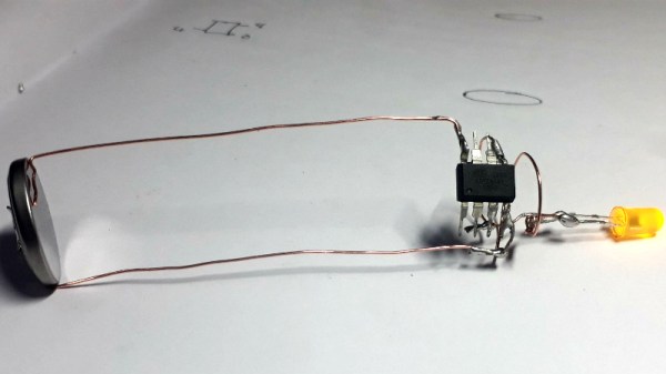
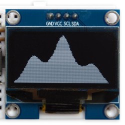
For his Hackaday Prize entry, [danjovic] is pushing whatever limits are left with the ‘tiny85. He’s using it as a test pattern generator, pushing out pixels to any old TV. The entire circuit is powered by a coin cell, and the entire thing fits in a Tic-Tac box.

The heart of the project, as you would expect, is a resistor ladder using all six available pins, using five for luminance and one for the sync. That is thirty-two shades of gray, if you’re keeping track. The trick is using the internal PLL and a bit of math to calculate the proper resistor values. The result is just a test pattern, yes, but [danjovic] managed to get a test pattern that has a resolution of 850 pixels across. That’s not bad by any measure.

Of course, if grayscale isn’t your thing, you can also use the ‘tiny85 to send Never The Same Color over the air or even push out the jams over a VGA port.