Converting A GameCube Controller To USB

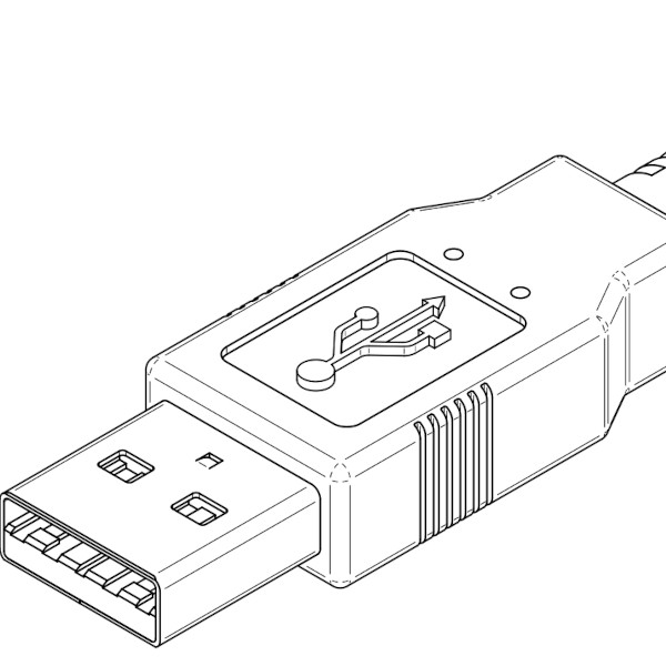
The GameCube controller is a favorite among the console enthusiasts new and old, and with Nintendo’s recent release of the Smash Bros. edition of this controller, this is a controller that has been in production for a very, very long time. [Garrett] likes using the GameCube controller on his PC, but this requires either a bulky USB adapter, or an off-brand GameCube ‘style’ controller that leaves something to be desired. Instead of compromising, [Garrett] turned his GameCube controller into a native USB device with a custom PCB and a bit of programming.

First, the hardware. [Garrett] turned to the ATtiny84. This chip is the big brother of the ubiquitous 8-pin ATtiny85. The design of the circuit board is just under a square inch and includes connections for the USB differential pairs, 5V, signal, and ground coming from the controller board.

The software stack includes the micronucleus bootloader for USB firmware updates and V-USB to handle the USB protocol. There are even a few additions inspired by [Garrett]’s earlier shinewave controller mod. This controller mod turns the GameCube controller into a glowing hot mess certain to distract your competitors while playing Super Smash Bros. It’s a great mod, and since [Garrett] kept the board easily solderable, it’s something that can be easily retrofitted into any GameCube controller.


ATtiny Watch Is Tiny

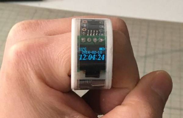
[陳亮] (Chen Liang) is in the middle of building the ultimate ring watch. This thing is way cooler than the cheap stretchy one I had in the early 1990s–it’s digital, see-through, and it probably won’t turn [陳]’s finger green.

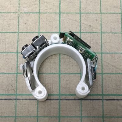
watch-gutsThe current iteration is complete and builds upon his previous Arduino-driven watch building experiences. It runs on an ATtiny85 and displays the time, temperature, and battery status on an OLED. While this is a fairly a simple build on paper, it’s the Lilliputian implementation that makes it fantastic.
[陳] had to of course account for building along a continuous curve, which means that the modules of the watch must be on separate boards. They sit between the screw bosses of the horseshoe-shaped 3D-printed watch body, connected together with magnet wire. [陳] even rolled his own coin cell battery terminals by cutting and doubling over the thin metal bus from a length of bare DuPont connector.

If you’re into open source watches but prefer to wear them on your wrist, check out this PIC32 smart watch or the Microduino-based OSWatch.

Solar-powered Weather Station Knows Which Way The Wind Blows

Bob Dylan may not have needed a weatherman to tell him when the wind blows, but the rest of us rely on weather forecasts. These, in turn, rely on data from weather stations, and [Vlad] decided that his old weather station was in need of an upgrade.

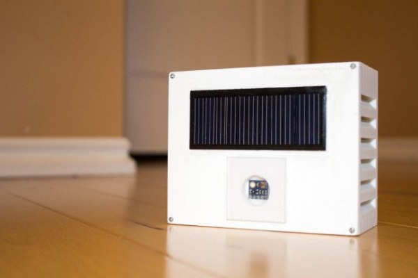
His station, which uploads live data to the Weather Underground, needed to be solar-powered, weather-proof and easy to install. He seems to have succeed admirably with this upgrade, which is built around an ATmega328 and the 433 MHz link from the old station. As part of the upgrade, he built a 3D-printed enclosure and installed all-new sensors on a home-made PCB that are more accurate than the old ones.

He looked into upgrading the wireless leg to WiFi, but found that the school’s WiFi had a login page that he couldn’t get around. So he re-used the old 433 MHz radio and connected the other end of the link to an old laptop on the wired network. Good enough, we say. Now how about a snazzy display to go along with it?

LED Tester Royale

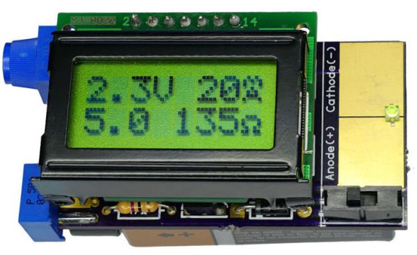
What do you get for the geek who has everything and likes LEDs? A tricked-out LED tester, naturally. [Dave Cook]’s deluxe model sports an LCD screen and two adjustable values: desired current and supply voltage. Dial these in, plug in your LED, and the tiny electronic brain inside figures out the resistor value that you need. How easy is that?

An LED tester can be as easy as a constant-current power supply, and in fact that’s what [Dave]’s first LED tester was, in essence. Set an LM317 circuit up to output 10mA, say, and you can safely test out about any LED. Read off the operating voltage, subtract that from the supply voltage, and then divide by your desired current to figure out the required resistor. It only takes a few seconds, but that’s a few seconds too many!

The new device does the math for you by adding an AVR ATtiny84 into the mix. The microcontroller reads the voltage that the constant current supply requires, does the above-mentioned subtraction and division, and displays the needed resistor. So simple. And as he demonstrates in the video below, it does double-duty as a diode tester.

This is a great beginner’s project, and it introduces a bunch of fundamental ideas: reading the ADC, writing to an LED screen, building a constant current circuit, etc. And at the end, you have a useful tool. This would make a great kit!

Continue reading “LED Tester Royale”

Father And Son Fix A Scale

It’s awesome when you can tag-team with your dad to fix stuff around the house. [Ilias Giechaskiel], with help from his dad, did a complete refurbishing of a broken bathroom weighing scale, but not before trying to fix it first. The voltage regulator looked bust. Powering the rest of the circuit directly didn’t seem to work, and none of the passives looked suspect. Most of the chips had their markings scratched off and the COB obviously couldn’t be replaced anyway.

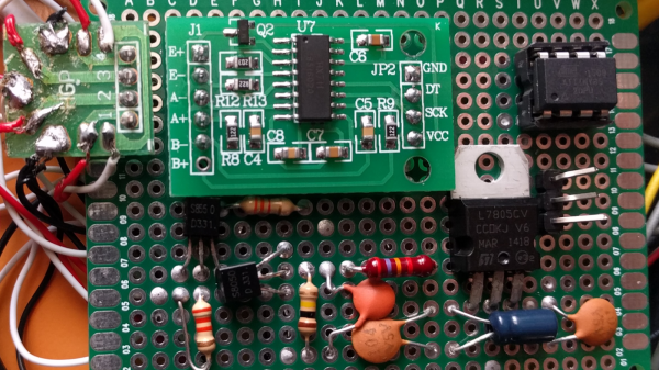
Instead of reverse engineering the LCD display, they decided to retain just the sensor and the switches, and replace everything else. The ATtiny85 seemed to have enough IO pins to do the job. But the strain-gauge based load cell, connected in a bridge configuration, did not have a signal span large enough to be measured using the 10 bit ADC on the ATtiny. Instead, they decided to use the HX711 (PDF) – a 24 bit ADC with selectable gain, specifically meant for use in weighing scales. Using a library written for the HX711 allowed interfacing it to the Arduino easy. The display was built using a 4 digit 7 segment display driven by the MAX7219. A slightly modified LEDcontrol library made it easy to hook up the display to the ATtiny. The circuit was assembled on a prototyping board so that it could be plugged in to another Arduino for programming.

Since they were running out of pins, they had to pull out a trick to use a single pin from the ATtiny to act as clock for the display driver and the ADC chip. Implementing the power-on and auto-off feature needed another interesting analog circuit block. Dad did the assembly of the circuit on a prototype board. In hindsight, the lack of IO pins on the ATtiny limited the features they could implement, so the duo are planning to put in an Arduino Nano to improve the hack. If you’re ever stuck with a broken scale, he’s made the schematic (PNG) and code available for use.

A Tiny Servo Motor Controller

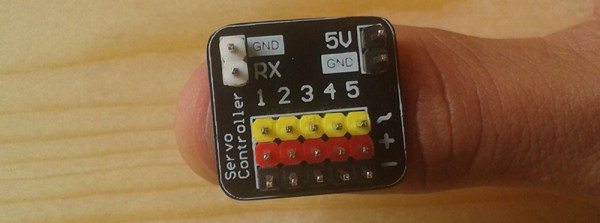
If you’re building a moving thing with a microcontroller, you’ll probably want to throw a servo controller in the mix. Driving a servo or two with a microcontroller takes away valuable cycles that just babysit the servo, making sure all the PWM signals are in sync. The thing is, most servo controllers are a massive overkill, and you don’t need that much to control a few servos over a UART. The proof of this is an attiny13 servo controller over on hackaday.io.

[arief] developed his tiny servo controller around one of the tiniest microcontrollers – the ATtiny13. This chip has just 1kB of Flash and 64 Bytes of RAM, but that’s enough to keep a few servos going and listen in to a UART for commands to drive the servo.

The construction of this servo controller board is simple enough – just a single sided board, microcontroller, and a few headers, caps, and resistors. Commands are sent to the ATtiny through a half duplex UART we covered before, with servos responding to simple serial commands.

If you’re building a robot army, this is the board to make. You’re going to need a high-powered controller to take over the world, but there’s no need to bog down that controller by babysitting a few servos.

ATtiny Does 170×240 VGA With 8 Colors

The Arduino is a popular microcontroller platform for getting stuff done quickly: it’s widely available, there’s a wealth of online resources, and it’s a ready-to-use prototyping platform. On the opposite end of the spectrum, if you want to enjoy programming every bit of the microcontroller’s flash ROM, you can start with an arbitrarily tight resource constraint and see how far you can push it. [lucas][Radical Brad]’s demo that can output VGA and stereo audio on an eight-pin DIP microcontroller is a little bit more amazing than just blinking an LED.

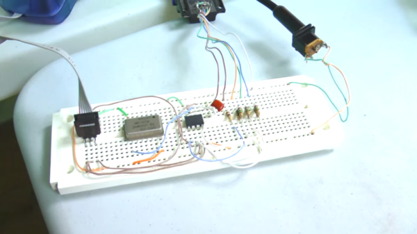
[lucas][RB] is using an ATtiny85, the larger of the ATtiny series of microcontrollers. After connecting the required clock signal to the microcontroller to get the 25.175 Mhz signal required by VGA, he was left with only four pins to handle the four-colors and stereo audio. This is accomplished essentially by sending audio out at a time when the VGA monitor wouldn’t be expecting a signal (and [lucas][Rad Brad] does a great job explaining this process on his project page). He programmed the video core in assembly which helps to optimize the program, and only used passive components aside from the clock and the microcontroller.

Be sure to check out the video after the break to see how a processor with only 512 bytes of RAM can output an image that would require over 40 KB. It’s a true testament to how far you can push these processors if you’re determined. We’ve also seen these chips do over-the-air NTSC, bluetooth, and even Ethernet.

Continue reading “ATtiny Does 170×240 VGA With 8 Colors”