[Ken Shirriff] Explains The TL431

[Ken Shirriff] had to get down into a bit of semiconductor physics to give us an explanation of the TL431, which he calls “the most common chip you’ve never heard of”. [Ken] may well be right about the TL431. Even Texas Instruments can’t nail down a single name for it. Their page for the part calls it a “Adjustable Precision Shunt Regulator”, yet the datasheet is titled “Precision Programmable Reference”. You’d think they’d have figured this out by now, considering the TL431 was launched in 1978.

TL431’s can most often be found hiding in switching power supplies. The Apple II switcher had one, and many current ATX supplies have 3. Uninformed parts scroungers may miss them, as they often hide in TO-92 or SOT-23 packages. The TL431 is no transistor though. The TL431’s operation is actually pretty simple. When the voltage at the reference pin is above 2.5V, the output transistor conducts. When the reference voltage falls below 2.5V, the device stops conducting. In a power supply, this operation would help the control electronics maintain a stable output voltage.

The real subject of [Ken’s] article is the layout of the TL431 on its silicon die.  Rather than bust out the fuming nitric acid himself, [Ken] uses some of [Zeptobars’] decapped chip images. Inside the TL431, [Ken] discovers that transistors aren’t made up of the three layer NPN or PNP sandwich we’ve come to know and love. In fact, the base isn’t even in the middle. Transistors, including the BJT’s used in the TL431, can be assembled in a nearly infinite number of ways.

[Ken] moves on to the resistors and capacitors of the TL431. The capacitors are formed two different ways, one as a reverse biased diode, and the other as a more traditional plate style capacitor. The resistors include fuses which can be blown to slightly increase the resistance values.

The takeaway from all this is that once you get down to the silicon level, it’s a whole new ball game. Chip layout may look a bit like PCB layout, but the rules are completely different. [Ken] mentions that in a future blog he’ll go into further detail on the operation of the TL431’s bandgap voltage reference. We’ll be watching for that one, [Ken]!

The Design And Fabrication Of A Digital Clock

boarddesign

This clock is the first thing that [Kevin] ever made, way back before the Arduinofication of making, and long before the open hardware community exploded, and before the advent of cheap, custom PCBs. It’s an elegant design, with six seven-segment displays, a time base derived from line frequency, controlled entirely by 74-series logic chips. There was only one problem with it: it kinda sucked. Every so often, noise would become a factor and the time would be displayed as 97:30. The project was thrown in the back of the closet, a few revisions were completed, and 13 years later, [Kevin] wanted to fix his first clock.

The redesign used the same 1Hz timebase to control the circuitry, but now the timebase is controlled by a DS3231 RTC with an ATtiny85. The bridge rectifier was thrown out in favor of a much simpler 7805 regulator, and a new board was designed and sent off to OSHPark. Oh, how times have changed.

With the new circuitry, [Kevin] decided to construct a new case. The beautiful Hammond-esque enclosure was replaced with the latest and greatest of DIY case material – laser cut acrylic. Before, [Kevin] would put a jumper on the 1Hz timebase derived from the line frequency to set the clock – a task that makes plugging a clock in exactly at midnight a much simpler solution. Now, the clock has buttons to set the hours and minutes. Much improved, but still an amazing look at how far DIY electronics have come in a little over a decade.


bc-22e ww2 reciever operating in a hotel

Dodgy Hotel, Beer And A WWII Era Tube Receiver

In the luxurious accommodations provided by Motel 8 and armed only with a few tools and a six pack – a pair of amateur radio enthusiasts attempted the repair of an old WWII era BC-224E receiver. They picked up the boat anchor antique receiver, which was in unknown condition, from a flea market while in town for the Dayton Hamvention, brought it back to their hotel and got to work.

The BC-224E came in two parts – the receiver and the power supply. The speaker for the system, which is actually located in the power supply, is driven by a large inductor.  Apparently when the receiver was constructed, the permanent magnets of the day were not powerful enough to drive a speaker.

Fortunately, the receiver also came with some schematics, allowing [Gregory] and his fellow radio enthusiast to reverse engineer the power supply. After a few tweaks and cap swaps, they crossed their fingers and plugged it in. Stay tuned to see what happened next.

Continue reading “Dodgy Hotel, Beer And A WWII Era Tube Receiver”

Sinclair ZX Spectrum +2A Slims Down

sinclair

[Carl] got his hands on a dead Sinclair ZX Spectrum +2A. He decided he wasn’t just going to fix it, he was going to improve it! The ZX Spectrum Compact is literally a “sawn-off” Spectrum +2A. [Carl’s] inspiration came from a similar mod at the Old Machinery blog.

Amstrad seems to have had a habit of bolting on additions to their products. In the case of the Spectrum +2A, it was a tape drive. Tapes weren’t a great storage method in the 80’s, and today they’re downright annoying. [Carl] didn’t need the tape interface, as he’s using a DiVide ATA interface.

The modification is rather straight forward. [Carl] broke out the hacksaw and cut the right end cap away from the tape drive. He then cut the entire tape drive away. The motherboard wasn’t safe from the saw treatment either, as the printer interface was cut off. Thankfully there were no components on the printer interface. Apparently [Carl] didn’t short any traces as he went to town with his saw.

With the motherboard modified to fit the abbreviated case, [Carl] was ready to begin reconstruction. He glued the cap onto the sawn-off case with Grip Fill glue, which also served to fill any gaps. Some sanding, priming, and painting later, The ZX Spectrum Compact was finished. This isn’t a perfect mod, as the gap is still slightly visible under the paint – but it’s good enough for [Carl]. Hey, it’s good enough for us, too – we can’t all be [Ben Heck]!


Emulating Touchscreens In Python

DOS

Software, especially DOS-based software meant for CNC control lasts forever, but hardware most certainly does not. When faced with aged and decrepit hardware meant for controlling a CNC machine that was slowly dying, [Oliver] needed something that would emulate 3M Microtouch touchscreen. Not wanting to go the hardware route, he decided to emulate a touch screen in Python.

The Python code is fairly simple, taking mouse input and translating it to the serial protocol the 3M Microtouch, and thus the old DOS CNC app, uses. Writing the Python to capture mouse clicks was only half of the problem, though. [Oliver] also needed a way to send these mouse clicks to an old DOS application. Virtualizing an old machine running DOS created a few timing problems, but a solution was eventually found with DOSBox and the Virtual Serial Port Emulator that can connect two applications with serial ports.

[Oliver] was finally able to get everything working, bringing this equipment back to life for at least another 30 years. Let’s just hope all the code is well documented and archived for the next guy.

NYC Resistor Gets A PDP-11/34

PDP-11/34 NYCR

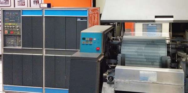
[Trammel Hudson] and NYC Resistor have gotten their hands on some old computing iron in the form of a PDP-11/34.  The PDP-11 is a 16 bit minicomputer made by Digital Equipment Corporation (DEC). Various incarnations of the PDP-11 were sold from the 1970’s all the way into the 1990’s. NYC Resistor’s model is has a label dating it to 1983.

The PDP was found in an old storage unit in the Bronx. Moving several racks of equipment across the city is no small feat, but NYC Resistor members have it done it so many times they’ve got it down to a science.

Once power is applied, a stock PDP won’t actually do anything until the boot loader is keyed in from the CPU front panel. Thankfully this particular PDP-11 had its boot instructions printed on a label on the CPU. NYCR’s machine also includes an M9312 “bootstrap / Unibus terminator” board, which allows the machine to boot at the push of a button.

The team connected the racks, terminals, and drives. Carefully following the instructions, they actually got their PDP to boot up! Their next step is to start reading in some of the old tapes that came with the machine. We’re all waiting with bated breath to see what “digitized monkey brains” contains. Once the machine is fully functional, we hope they get it on the internet and load up The Hackaday Retro Edition.

Continue reading “NYC Resistor Gets A PDP-11/34”

Johnny Mnemonic, Broken Columns, And Pinball Repair

johnny

[Quinn Dunki] has come to realize the pinball machines of her youth aren’t the lame games she remembered. They’re actually quite marvelous in terms of electronics, mechanics, engineering and the all important hackability. Wanting to pick up a 90s dot matrix display pinball machine and being a [William Gibson] fan, [Quinn] picked up an old Johnny Mnemonic machine. She’s already looked into replacing the incandescent bulbs with LEDs, and has just wrapped up troubleshooting a broken plasma dot matrix display.

dotsThe neon dot matrix displays in pinball machines of this era are finicky devices with a lot of stuff that can go wrong. On powering the display up, [Quinn] noticed a few columns on the left side of the display weren’t working. These machines have great diagnostic menus, so running a test that displays a single column at a time revealed two broken columns. However, when a solid fill test was run, all the columns work, save for a few dots in the upper left corner. This is an odd problem to troubleshoot, but after more tests [Quinn] realized dots in column five and six only work iff both adjacent dots in the same row are lit.

The power supply seemed okay, leaving the problem to either a logic problem, or something wrong in the glass. With a meter, [Quinn] deduced there was a short between the two broken columns, and tracing every thing out revealed a problem in the hermetically sealed display filled with noble gasses. A replacement display was ordered.

While [Quinn] was replacing the display, she decided it would be a good time to rehab the almost-but-not-quite out of spec driver board for the display. The power resistors had scorched the PCB, but didn’t damage any traces. Replacing the parts with modern components with a higher power rating brought the board back to spec with components that should last longer than the 20-year-old parts previously inhabiting the driver board.

It was a lot of effort, but now [Quinn] has a brand new display for her pinball machine and is ready to move on to the next phase of her restoration.