Floating Globe, Hacked To Rotate

they need to hire this guy

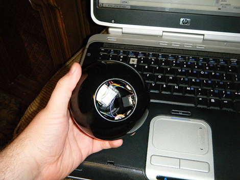
[Alexy Sha] has done this fantastic hack, where he modified a magnetic floating globe to be motorized and spin on a tilted axis. The original globe was simply levitating via a magnet mounted inside. Though you could spin it by hand, it wasn’t motorized, and actually floated completely vertically instead of being tilted.

[Alexy] wanted to take this idea further and make it automatically spin on a rotated axes. He built a rotation assembly that was basically a motor, hung off-center, attached at the center of the globe. He had to power it via a coil hidden in the base unit, so that it could remain light enough to float. He did a fantastic job and the final product seems like it is the true way it should have been sold.

Check out a video of it in action after the break. We actually like the spinning ring, when he’s testing it, just as much as the final spinning globe.

Continue reading “Floating Globe, Hacked To Rotate”

Pressure Mapping Sensor Mat

[imsolidstate] built his own pressure sensitive mat. It utilizes two discs of copper clad board with a piece of foam in between for each of 64 sensors. As the foam gets compressed, the capacitance between the two pieces of copper changes, a measurement that is fairly easy to make with an analog to digital converter. The mat is being used to measure how well a horse saddle fits the animal. Data is read in through a serial port and then mapped using Excel. This prototype proves that the concept works but [imsolidstate] mentions that there’s room to improve the sensitivity and that there could be more noise filtering incorporated into the design.

USB Typewriter

clickety-clackity-clickety-clackety-DING

[Jackzylkin] has posted an instructible showing, in detail, the process of creating a USB typewriter. He takes us through the process of disassembling the typewriter, mounting all the sensors where the little hammers strike, and wiring it all up to a custom board to interface with the computer via USB. While he is selling the board, the schematics are available if you want to build your own. We think the clickety-clack of a real typewriter could be very satisfying to the touch, though it might drive your co workers insane. The younger ones might also quiz you as to what that archaic machine is. We’ve actually seen this done before, way back in 2005.

Make Switched-mode Power Supplies Do Your Bidding

[Ken] needed to supply 3.3 volts of regulated power. He started by using a linear voltage regulator but after a few calculations he discovered that 72% of what he put in was lost to heat. The solution to this is a switched-mode power supply. Rather than burn off energy through a voltage divider, an SMPS turns the power on and off very quickly to achieve the desired voltage.

A car charger-type USB regulator was chosen as [Ken’s] donor device. He figured that making adjustments to the resistors inside would affect the output voltage and he was right. He adjusted the potential divider and ended up with a steady 3.295V.

We asked him to share the schematic that he put together from studying the board and he came through. See that and get the link to the DC-DC converter datasheet after the break. Continue reading “Make Switched-mode Power Supplies Do Your Bidding”

Prototyping The Bulbdial Clock

Evil Mad Scientist posted a story about what went into developing the Bulbdial clock. We think the Bulbdial is one of the best pieces of kit out there for many reasons; using colored shadows for each hand is a brilliant idea, the design is clever and uses a low parts count, and the concentric rings that make it work also add to the aesthetic. But after seeing the original wood prototype it had crossed our minds that developing those circular PCBs isn’t the easiest thing to pull off. To save on board cost, the first run didn’t have the center routed out, but rather used almost-touching holes drilled during manufacture and finished by hand during assembly. They also go on to discuss the use of Charlieplexing to reduce part count and the search for a suitable diffuser for the clock face.

Gas Plasma Pinball Display

[Whoopjohn] decided to build a driver board for a display he pulled from a pinball machine. You’ve probably seen these used to scroll both score and messages using a total of sixteen 15-segment digits. We’d love to get our hands on one, and you might too but where? [Whoopjohn] notes that these were usually installed two-per machine and the driver boards were run close to their maximum ratings. That means that somewhere there’s a collection of broken machines with working displays. If you do plan to make this happen, you should be able to figure out the circuit based on this commented board layout (pdf).

FPSLIC Powered LED Matrix

[Mathieu] built this display in hopes that he can play pong on it. You can imagine the headache that awaits when trying to figure out how to drive the 6144 bi-color LEDs. I must have worked out because the thing looks great in the video after the break. The solution he chose was a bit unfamiliar to us though. He used a Field Programmable System Level Integrated Circuit produced by Atmel, or FPSLIC. This is a kind of mash-up of components we’re more accustomed to.

The AT94K is a single chip that houses an 8-bit AVR microcontroller, and FPGA, and SRAM. This project uses that FPGA to handle the multiplexing of the display via code written in VHDL. The AVR core receives data via a USB port, stores two images in the SRAM (one for each LED color), and then outputs it to be drawn on the display. On second thought, this project sounds like fun and it’s a great way to get start learning that VHDL you’ve been putting off. Continue reading “FPSLIC Powered LED Matrix”