Xbee Controlled, Granite-wrapped Clock Travels Into Future

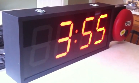
From the looks of it this clock is a couple of months ahead of its time. [Oscar] built the clock (translated) taking time to add a lot of goodies into the mix. First up, the parts you see include six large 7-segment displays for hours, minutes, and seconds as well as an LED marquee which can scroll messages. Inside there’s a temperature and humidity sensor for environmental feedback, and an Xbee module which allows for wireless computer control. Time is kept by a DS1307 real-time clock, which is read by an Arduino Uno, then pushed to the display by the pair of I2C addressable SAA1064 drivers. The whole thing was enclosed in four sheets of granite for the box, and a pane of glass for the front. We sure hope it’s well anchored to that wall. You can see it ticking away after the break.

Continue reading “Xbee Controlled, Granite-wrapped Clock Travels Into Future”

Edison Clock Uses Ammeter Plus Bulbs To Set Alarm

This is the Edison clock, designed by [David Krawczyk]. It shows time in the same way as the multimeter clock, regulating power to two analog needle meters. The feature that makes this one a bit different is the alarm. You can see the series of holes on the front of the base. These have a small light bulb socked in each, and correspond to hours and 5-minute increments. Insert two bulbs to set the alarm time, and make sure that the alarm knob points to ‘on’. As you can see above, the alarm has been set to 8:15. Hidden on the last image of the article above is a PDF with just a bit more explanation. Still, much has been left out so if you replicate this clock we want to hear about it.

[via Gizmodo and Walyou]

Binary Clock Using Logic Chips And Mains Frequency

[Osgeld] built himself a binary clock. He didn’t take the time to explain his project, but he did post beautifully hand-drawn schematics and pictures of the circuit (PDF) as he was building it. We’ve seen clock projects that use mains frequency as the clock source and that’s the route that [Osgeld] chose for his build. He started with a 9-12V AC wall wort as a power input. From there it’s just a matter of using a bridge rectifier to convert to DC, then a 7805 linear regulator to establish a steady 5V rail. A resistor and a couple of diodes allow him to pull the 60 Hz frequency off of the incoming AC, and then use a combination of 4000 and 7400 logic chips to count the pulses and keep track of the time.

Atomic Pinball Clock

[Mark Gibson] sent us a load of details on his build, a WWVB atomic clock using a pinball machine marquee (PDF). This is the upright portion of an old machine that used electromechanical displays instead of digital electronics. It’s big, noisy, and seeing it running might make you a bit giddy. Luckily he included video that shows it working on both the outside and the inside.

It took a bit of probing to discover the connections for relays that control the display. From there he used optoisolation to drive them with an Arduino. With this hurdle behind him, [Mark] set out to add atomic clock accuracy. He picked up a WWVB module and added it to the mix.

Check out his build log in PDF form linked above. He went out of his way to explain how the original parts work, and the processes he used during prototyping. For more of those juicy details we’ve added a photo gallery and his video after the break.

Didn’t get enough pinball goodness from this project? Check out the this digital gas plasma display pulled and reused from a much more modern pinball machine. Oh, and there’s always Bill Paxton Pinball.

Continue reading “Atomic Pinball Clock”

Driving An 8-digit Split Flap Display

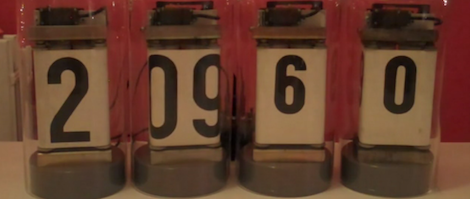
[Markus] got his hands on a split-flap display and built a controller for it. These sometimes can be found on really old alarm clocks, but [Markus] was a lucky-duck and managed to acquire this large 8-digit display which previously made its home in a railroad station. They work like a Rolodex, mounting flaps around a cylinder for a full alpha-numeric font set.

A PIC 12F683 was selected to control the display, using optoisolation to separate the 42V display motors from the driver circuit. From the video after the break we think he did a wonderful job of getting this working. It only takes six I/O pins to control and the sound and look of the digits scrolling leaves us quite jealous.

So what’s he got in store for it? The first thing he did was use it to count down to the New Year.

Continue reading “Driving An 8-digit Split Flap Display”

Bi-color LED Matrix Clock Uses Point-to-point Construction

[Daniel] wanted his child to stay in bed until a semi-decent time each morning. The problem is the kid doesn’t know how to read a clock, so [Daniel] built him a clock. Yeah, doesn’t make much sense to us either, but we’ve used our own shaky premises for projects so who are we do judge?

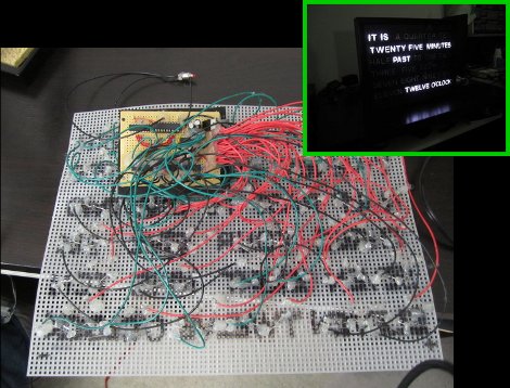
He used a bi-color 8×8 LED matrix as the clock display. What caught our eye is the point-to-point soldering he used for the three strip boards that make up the device. Note the use of a drill-bit to break the traces when needed. Each board has its own purpose; the matrix drive, the logic board, and the power board. A PIC 18F4550 lets [Daniel] control the clock via USB, and takes care of lighting up the hour as a red number when it’s time to sleep, and a green one when it’s okay to arise. There’s a flashing pixel for seconds, and a binary readout of minutes along the bottom.

We’ve asked [Daniel] to post a schematic and an image of the clock face when displaying the time. No word yet but we’ll keep our eye on it. In the mean-time, check out this clock that uses an RGB 8×8 LED matrix.

Alarm And Wake Up Light

On the shortest day of the year wouldn’t it be nice to wake up to a bright room? This alarm clock with an integrated wake-up light is one way to do just that. It has some nice features, like a wood veneer that allows the seven-segment display to shine through, but hides it when the display is turned off. There’s also a feature to adjust the color based on ambient room temperature (another way to dwell on how cold it is in your bedroom).

A CC1101 RF chip came to the party, but we can’t figure out what it’s purpose is in this circuit. If you can shed some light on its involvement please do so in the comments.

[Thanks Eric]