clock hacks979 Articles
Fake Nixie Clock

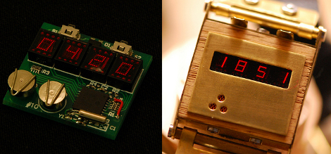
[Barry] didn’t want to deal with the voltages involved in using a Nixie display so he built this clock to look like it has Nixie tubes. He’s made 7-segment LED displays using some channel material, and mounted them so they look like they’re hovering above the clock base. Once everything was hooked up he added small glass jars over the top of each digit, completing the look.
Six Digit LED Clock

Got a bag of LEDs handy? Why not build a display with them? We’ve seen a lot of clocks that make use of LED modules but soldering your own is a fun pastime. [Vadim Suhovatih] did just that using 130 LEDs to build this clock. Each segment of the 7-segment digits consists of three LEDs in parallel which are switched by some 2N4401 transistors. An ATmega328 in the form of an Arduino controls the device with the aid of a DS1307 real-time clock for timekeeping and a 4017 decade counter to assist with scanning the display. Check out the demo after the break.
Talking Clock Sounds Just Like You
[vimeo=http://www.vimeo.com/10852914]
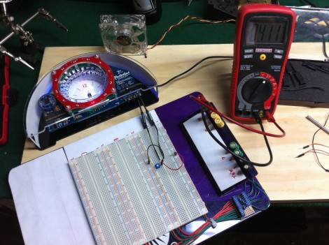
We’d bet a large portion of our readers don’t remember when you could call the phone company and get the time of day. Gadget Gangster is bringing back the tried and true method with this talking clock. Just press the button and the ‘operator’ will read the time of day to you. Record your own voice and place the WAV files on an SD card, from there a Propeller chip takes care of the rest.
As a side note, we’re big fans of the method used to breadboard the power supply using the TO-220 package leads as their own jumpers. We’ve always been partial to using a breadboard regulator on a PCB but this method is simple and takes almost no space at all.
Biopunk Watch: Time, Temperature, Gaming

[Matthew Garten] built this watch based on an Arduino. The face is a small color display which allows you to choose to show time in digital, binary, or analog formats. In keeping with the recent trend here on Hackaday he has a glove-based add-on that has temperature sensors in the fingers; for Firefighters or those with nerve damage to their fingers (we’re thinking Darkman). For entertainment in any situation he’s included a trackball and the ability to play breakout or draw in 16-bit color. Details are scarce but apparently he’ll be sharing more soon. For now, watch the video after the break and think of ways to shrink this down into a nice package like the Pong Watch enjoys.
DPAC Put Your Alarm Clock To Shame

DPAC, the Dynamically Programmable Alarm Clock, goes far beyond what you would expect an alarm clock to do, yet we find all of its features useful. You can see there are four buttons at the bottom that control the menu scrolling. The second from the left currently reads “Sync”, a feature that the clock uses every 10 minutes but can be forced manually. This will check your Google Calendar, schedule an alarm for the next event while factoring in driving distance, traffic, and weather conditions. It’s got an audio system for radio and iPod operation, but also includes some home automation options. Using the X10 communication protocol it can turn on lights, start the coffee maker, and open the blinds as part of a gentle wake-up cycle. All of this is configurable through the clock itself, or via the web interface. The prototyping was done on an Arduino but the final version uses an AVR ATmega324 along with a Roving Networks RN-134 WiFi module (datasheet) for connectivity. Check out the demonstration video that [Eric Gaertner] and his fellow developers filmed after the break.
Using A/C Frequency As A Clock Signal
A while back we saw a logic clock that used the alternating current frequency from the power grid to keep time. We asked for information on your projects that use this method and we got a lot of comments and tips. Today we’re sharing [Doug Jackson’s] method which he used in his word clock.
The schematic above is from that project and we’ve outlined the important part in green. [Doug] pulls a signal from the 9V AC power before it hits the bridge rectifier, using a 100K resistor and a zener diode to protect the microcontroller pin. The code for that project comes as a hex file but he sent us the C code pertaining to this timing circuit. It’s written for PIC but you’ll have no trouble adapting it to other microcontroller families. Take a look after the break.