I’m a firm believer in using the right tool for the job. And one of the most fantastic things about open-source software tools is that nothing stops you from trying them all. For instance, I’ve been going back and forth between a couple, maybe three, CAD/CAM tools over the past few weeks. They each have their strengths and weaknesses, and so if I’m doing a simpler job, I use the simpler software, because it’s quicker and, well, simpler. But I’ve got to cut it out, at least for a while, and I’ll tell you why.
The first of the packages is FreeCAD, and it’s an extremely capable piece of CAD/CAM software. It can do everything, or so it seems. But it’s got a long shallow learning curve, and I’m only about halfway up. I’m at the stage where I should be hammering out simple “hello world” parts for practice. I say, I should be.
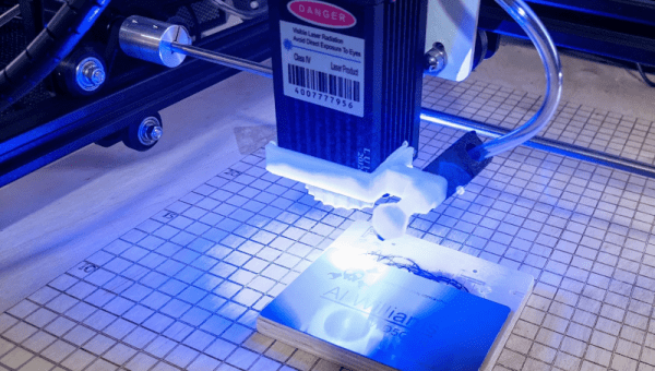
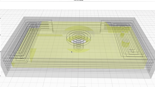
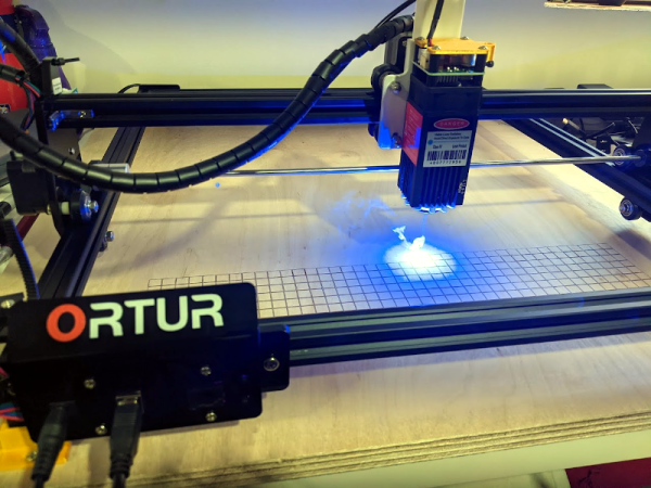
 Fortunately/unfortunately, some Hackaday readers introduced me to KrabzCAM through the comments. It’s significantly less feature-full than FreeCAD, but it gets the job of turning your wife’s sketches of bunnies into Easter decorations done in a jiffy. For simple stuff like that, it’s a nice simple tool, and is the perfect fit for 2D CAM jobs. It’s got some other nice features, and it handles laser engraving nicely as well. And that’s the problem.
Doing the simple stuff with KrabzCAM means that when I do finally turn back to FreeCAD, I’m working on a more challenging project — using techniques that I’m not necessarily up to speed on. So I’ll put the time in, but find myself still stumbling over the introductory “hello world” stuff like navigation and project setup.
I know — #first-world-hacker-problems. “Poor Elliot has access to too many useful tools, with strengths that make them fit different jobs!” And honestly, I’m stoked to have so many good options — that wasn’t the case five years ago. But in this case, using the right tool for the job is wrong for me learning the other tool.
On reflection, this is related to the never-try-anything-new-because-your-current-tools-work-just-fine problem. And the solution to that one is to simply bite the bullet and stick it out with FreeCAD until I get proficient. But KrabzCAM works so well for those small 2D jobs…
A hacker’s life is hard.